We saw in a previous blog the difficulties in error calculations when using meter test benches without any electronics.
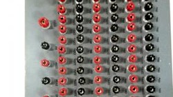
Now meter testing is much more comfortable. Actually you only need to put the meters on the rack. For testing big quantities of meters a robot can also do the job.
But what happens inside?
Power generation
The meter test equipment uses digital amplifiers to generate voltages and currents. For the fans of analog technology we still have analog amplifiers. Comparison measurements with both technologies are showing differences less than 5 ppm (parts per million).
The amplifiers are controlled by a waveform generator, frequency generator, controller or whatever name the manufacturer has given to this device.
In CLOU terminology it's a controller.
This controller receives the settings information from the PC software and calculates the waveform, amplitude, frequency, phase-shift and harmonics. This information is send to the individual amplifiers to perform the accurate settings.
Reference Standard
The reference standard is the heart of the meter test system. It monitors the accurate settings of the test values and generates power-proportional pulses for the error measurement. (We skip for now the other tasks of the reference standard:)
How to understand power proportional pulses?
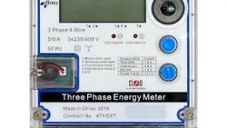
A electronic meter is making energy-proportional pulses. You remember the term "meter constant". A energy meter with a constant 1000 i/kWh is flashing 1000 times per kWh.
The reference standard has also at least one constant. Typically it has an individual constant for each range-pair. The unit is frequency per power.
| CL3115 power constants | ||||
|---|---|---|---|---|
| 60 V | 120 V | 240 V | 480 V | |
| 0.01 A | 2 x 10⁹ | 2 x 10⁹ | 2 x 10⁹ | 2 x 10⁹ |
| 0.02 A | 2 x 10⁹ | 2 x 10⁹ | 2 x 10⁹ | 2 x 10⁹ |
| 0.05 A | 2 x 10⁹ | 2 x 10⁹ | 2 x 10⁹ | 2 x 10⁹ |
| 0.1 A | 2 x 10⁹ | 2 x 10⁹ | 2 x 10⁹ | 2 x 10⁹ |
| 0.2 A | 2 x 10⁹ | 2 x 10⁹ | 2 x 10⁹ | 2 x 10⁹ |
| 0.5 A | 2 x 10⁹ | 2 x 10⁹ | 1.6 x 10⁹ | 8 x 10⁸ |
| 1 A | 2 x 10⁹ | 1.6 x 10⁹ | 8 x 10⁸ | 4 x 10⁸ |
| 2 A | 1.6 x 10⁹ | 8 x 10⁸ | 4 x 10⁸ | 2 x 10⁸ |
| 5 A | 6.4 x 10⁸ | 3.2 x 10⁸ | 1.6 x 10⁸ | 8 x 10⁷ |
| 10 A | 3.2 x 10⁸ | 1.6 x 10⁸ | 8 x 10⁷ | 4 x 10⁷ |
| 20 A | 1.6 x 10⁸ | 8 x 10⁷ | 4 x 10⁷ | 2 x 10⁷ |
| 50 A | 6.4 x 10⁷ | 3.2 x 10⁷ | 1.6 x 10⁷ | 8 x 10⁶ |
| 100 A | 3.2 x 10⁷ | 1.6 x 10⁷ | 8 x 10⁶ | 4 x 10⁶ |
The output frequency for end of range in voltage/current pair with three phase connection is 160 kHz. The power pulses are on TTL/CMOS level. The burden capacity is > 20 mA.
Calculation formulas
Frequency
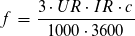
UR = voltage range
IR = current range
c = reference meter constant
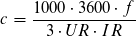
Constant
Example for pulse frequency
We have a voltage of 230 V and a current of 3 A. What will be the power proportional output frequency?
The reference standard is running in auto-mode. So it selects the range pair 240/5 A. The constant for this pair is 1.6x 10⁸ pulses/W (taken from the table).
Now we use our frequency formula
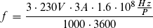
The power proportional pulse frequency is 92 kHz, equivalent to the power of 2070 W (3x 230 V * 3 A). If the power is not stable the frequency is changing.
So when we know the number of pulses over a certain time, we know the average power during this period.
Error calculation
Meter test benches have an error calculator for each measurement position. This error calculators get the power-proportional pulses from the reference standard. They also get the energy meter pulses from the scanning heads. From the test bench control software the error calculators know the actual meter constant for each position.
With this informations the error calculators are operating in the same way like we did manually in the past.
This article is simplified.
If you have specific questions, just put a comment.
Thank you for reading.
Editor's note: This article was originally published in December 2019 and has been updated for comprehensiveness.

what can cause a tramsformer operated meter rated at Imax 4A and programmed at 1250/1A,11000/110v fail on Imax or any current above 1A? could it be due to scanning head not able pick the pulses
Thank you for the interesting question. When we look into the IEC62052-11, chapter 5.11.1, we see: "The maximum pulse frequency shall not exceed 2,5 kHz."
An error measurement system from famous brands like MTE, ZERA or CLOU can easy match with this flashing frequency.
So either the pulses are not picked by the scanning head or the meter can not process the pulses for maximum load internally.
I have tested our portable calibrator RS350 for fun with 8 kHz. So maybe you make a error measurement on maximum load with this device or with an MT320 (should also work fine).
You can also calculate the theoretical flashing frequency of the test output based on the meter constant to see whether it exceeds 2.5 kHz on maximum load.
Please let our readers know the cause. I suppose others will have the same question.
Thank you