
![]() This article is intended for experienced utility metering engineers. The content assumes a high level of expertise in electrical metering and advanced system diagnostics.
This article is intended for experienced utility metering engineers. The content assumes a high level of expertise in electrical metering and advanced system diagnostics.
In the complex world of electrical systems, accurate energy metering is essential. However, incorrect wiring of meters can lead to skewed energy readings, particularly in reactive energy measurements. For electrical engineers, decision-makers, and testing engineers, understanding these wiring issues is crucial to ensure precise and reliable energy data.
Key Meter Wiring Issues and Their Impact
Swapped Current and Voltage Phases
One prevalent error is the swapping of current and voltage phases. When the current transformer (CT) for phase L1 is connected to the voltage for phase L2, it disrupts the phase angle measurements. This misalignment often results in erroneous reactive power calculations, leading to inflated reactive energy readings. Ensuring that each CT is correctly matched with its corresponding voltage phase is essential to avoid this pitfall.
Incorrect Polarity of Current Transformers (CTs)
Maintaining the correct polarity of CTs is another critical aspect. Each CT has a defined polarity that must be adhered to during installation. If the polarity is reversed, it causes incorrect current direction detection, adversely affecting active and reactive power calculations. This can lead to misleading readings, often indicating higher reactive energy than is actually being consumed.
Neutral and Earth Connections
Improper handling of neutral and earth connections can also lead to significant issues. When the neutral is connected to the earth at multiple points, it can create circulating currents that affect meter readings. This results in higher than expected reactive energy measurements due to additional, unintended paths for current flow. Proper separation and connection of neutral and earth wires are crucial to avoid these complications.
Shared Neutral Conductor
In systems where a neutral conductor is shared among multiple circuits, high resistance in the neutral can cause voltage drops and imbalances. This, in turn, leads to erroneous meter readings, particularly affecting reactive power measurements. Ensuring that each circuit has a dedicated neutral or that the shared neutral is adequately sized and maintained is vital for accurate metering.
Incorrect CT Ratios
Using CTs with incorrect ratios can distort meter readings. If the CT ratio does not match the meter's settings, it leads to incorrect scaling of the measured current, affecting both active and reactive power calculations. This issue can be especially pronounced in systems with varying load profiles. Verifying that CT ratios are correctly set is a necessary step in achieving accurate energy measurements.
Diagnostic and Corrective Measures
To diagnose and rectify these issues, several steps can be taken:
- Visual Inspection
Begin with a visual inspection of the wiring to ensure that CTs and voltage connections are correctly matched and that the polarity is maintained. - Verify CT Ratios
Check that the CT ratios match the meter's settings. - Measure Voltage and Current
Use a portable meter to measure voltage and current directly at the meter terminals. Compare these readings with the meter's displayed values to identify discrepancies. - Check for Neutral Issues
Measure the voltage drop across the neutral conductor and ensure that it is minimal, indicating low resistance. - Phase Sequence Verification
Ensure that the phase sequence (L1-L2-L3) is consistently maintained in the meter and the connected load.
Practical Example
Imagine a facility with several three-phase motors, where the reactive energy readings are suspiciously high. Upon inspection, you might find that the CT for phase L1 is connected to the voltage input for phase L2. This mismatch causes the meter to calculate a phase angle that is not representative of the actual load, skewing the reactive power measurement. By correcting the connections, the meter will then accurately measure the phase angle, providing correct readings for both active and reactive energy.
Takeaway
Understanding the causes of high reactive energy readings and implementing corrective measures is essential for accurate energy measurement and system efficiency. Incorrect meter wiring, poor power factor, harmonics, capacitive loads, and meter calibration issues are common culprits that need to be addressed. By focusing on power factor correction, harmonic filtering, regular meter calibration, load balancing, and correct wiring practices, these issues can be mitigated.
The suggested tests and regular verifications can be effectively conducted using our on-site calibrators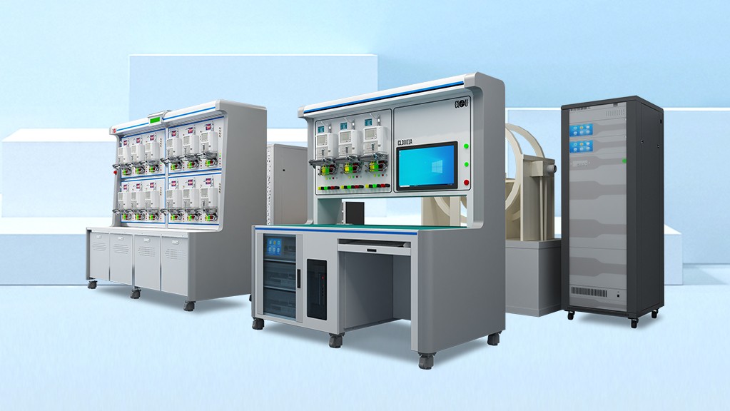 Introducing Our High-Quality Meter Test Equipment for Precise Measurements They are designed to provide accurate and reliable measurements, ensuring that your electrical systems are functioning optimally. With advanced features, on-site tests simplify the process of identifying and correcting wiring issues, making it an invaluable tool for any experienced utility metering engineer.
If you have any inquiries or need further information about our on-site meter test equipment, please do not hesitate to reach out Contact Us to us. We are here to assist you and welcome your valuable thoughts and comments.
Until then, keep shining bright like a solar panel on a sunny day!
Editor's note: This article was originally published in June 2024 and has been updated for comprehensiveness.


All comments are moderated before being published. Inappropriate or off-topic comments may not be approved.