
When we talk about power we always need to indicate the direction and which sort of power.
We can have:
- Active power, P
Active power is expressed in watt (W). Sometimes this power is also called "real power"
This is the power you are actually consuming. - Reactive power, Q
Reactive power is expressed in volt-ampere reactive (var)
This power is stored in components, then released again back to the source through the AC cycle. Capacitors and inductors do this. - Apparent power, S
Apparent power is expressed in volt-ampere (VA)
(RMS voltage times the RMS current). A power supply must be capable to output the full apparent power delivered to a circuit, not just the active power.
Quadrant I
Quadrant I is defined as an area where both powers flow positively. Both are delivered to the consumer load. In many cases the CLOU terminology is forward. The power factor is lagging, we have inductive influence.
The IEC literature is using the term import.
In this quadrant we have Import of active power and Import of reactive power.
Quadrant II
In quadrant II, reactive power is positive and active power flows negatively. In many cases the CLOU terminology is reversed. The IEC literature is using the term export.
Quadrant III
In quadrant III, reactive and active power flow negatively (both powers are received from the customer). This is also a export condition.
Quadrant IV
In quadrant IV, reactive power flows negatively, and active power flows positively. This is a import condition.
The interactive diagram below shows the relationship between the phase angle φ, apparent-, active- and reactive power respective energy. The diagram is in accordance with clauses 12 and 14 of IEC 60375. Reference is the current vector (fixed on right-hand line, 0°). The phase angle φ between voltage V and current I is taken to be positive in the mathematical sense (counter clockwise).
Four Quadrant Simulation (IEC62053-23)
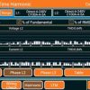
Geometric representation of active and reactive power
Note: The sine-wave diagram was changed to mathematical expression with reference on current (green). The oscilloscope view with reference on voltage was leading to misunderstanding. (24.11.2020)
Thank you for taking a look and for valuable comments.
Editor's note: This article was originally published in July 2019 and has been updated for comprehensiveness.


I may have a question . In the fourth quadrant measurmement of multi function energy meter power is deliverd to the customer so do we take energy reading at the first quadrant only .
For active energy to the customer, you read the A+ register (OBIS 1.8.0 for total, or 1.9.0 for the billing period). If you are also billing reactive energy, you read the Q+ register = Q1 + Q2 (OBIS 3.8.0 for total, or 3.9.0 for the billing period).
Yes, I agree, but I am asking in a more practical context. Power lines have certain impedances on which voltage drops/increases may occur (depending on the direction of power flow). In addition, there is also the phenomenon of resonance of the inductive and capacitive element – in the case of a certain relation of the value of both elements, there may be an increase in voltage in the circuit.
From the power line side, you are right. The voltage will drop with the length of the line. The harmonic resonances are depending on the load situation. There is no general solution. You need to monitor your network and apply filters to avoid resonances. For large scale grids, you better use a network model for analysis.
Example: We have an asynchronous induction generator (which draws reactive power from the network to work). If it works in generation mode (gives active power to the network) we can expect its work in the third quarter, right? Reactive power is then conventionally treated as an export, so the network voltage will increase because of this? And vice versa – if, for example, we compensate for this generator with a capacitor and go to quadrant number II, will the voltage tend to decrease (reactive energy import)?
Thank you for your question. The voltage remains the same. Compensation does only change the phase shift between voltage and current.
Hello
Thanks for the article but I have a question , if the meter connection is just reversed and the flow of current from Grid to Houses , should the meter record the consumption it as Export energy ?
Thanks for your question, Mak.
The measurement element inside the meter just records the consumption and the direction. So, when the connection is reversed, the meter counts import as export.
Since this is most likely the oldest method for tampering, all energy meters have a provision to count a reversed flow in the import register. This is the default setting to avoid losses for the power companies. If you have your own power generation (wind/solar) and feed back to the grid, you'll get a four-quadrant meter to balance your consumption with your production.
Hi,
Help me understand. Q1 and Q4 power is consumed and Q2 and Q3 power is fed back to the grid or export.
From other materials this explanation contradicts and i agree with them.
Q1 and Q3 acts as imports or power is consumed and Q2 and Q4 as exports
This is the reason why agree with this explanation ;
Q1 power is +ve (V&I) – hence VxI = S positive (import)
Q2 Power is -ve (V&-I) – hence Vx-I =-S negative (export)
Q3 Power is +ve (-V&-I) – hence -Vx-I =S positive (import)
Q4 Power is -ve (-V&I) -hence -VxI = -S negative (export)
This contradicts what you have shared . Please advise.
Thanks for your comment and good elaboration. We are here referring to the IEC representation model, where the current is fixed on 0° (import) or 180° (export).
This definition is in place since year 2003.
You are referring to the model where the reference is voltage. It's in some parts of the world in use, but not according to the International Electrotechnical Commission (IEC). When you read the comments, you can find a link posted by our reader Nick. There you can find your model.
Always keep an eye on the reference.
thanks alot of information
Thanks for reading and kind comment.
I'd like to revisit a question asked earlier. In Quad1 and Quad2 the voltage leads the current (current lags the voltage). Why are not both of these two quadrants labeled inductive?
Thanks for coming back, William.
The IEC IEC62053-23 model is based on current as reference.
In quadrant 1 we have import (P+) with a lagging current.
In quadrant 2 the flow direction is export (P-).
So the current is leading the voltage.
Hi,
In what circumstance the export can happen, considering a power factor correction capacitor bank with the series reactor. Sometimes analyzer showing -92 Deg. and export in one of the phases. Is it a tuning issue?
Seems you have overcompensated the system. Best praxis is to compensate only by 95%. If you have a 100% compensation, you will face reverse currents on low inductive loads. Some fine-tuning is recommended.
MUY CLARA SU REPRESENTACION, GRACIAS
Thanks for taking a look and kind comment.
So the vector Ua (voltage L1) follows the vector of the apparent Power S. Is my opinion correct?
Mike, you are right. You can also take a look at the vectorial representation for voltage and current. When we look at the formula (S = U * I) we see that S is following U and I.