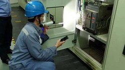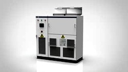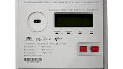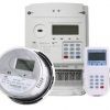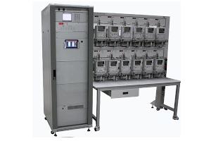
The three phase test bench CL3000 consists of a source cabinet and a meter rack. The typical use is to calibrate energy meters.
Typical configurations for a meter rack are 10 positions or 20 positions. We make the racks ourself, so other nos. of positions are easy possible.
The photo shows a rack with 12 positions.
Main Hardware Components, Source
Reference Standard CL3115

The reference standard CL3115 has accuracy class 0.02
It can also be used as stand-alone equipment. See the full description here.
Server CL2018
The server is connected to the PC (or tablet) via ethernet-cable or WiFi and keeps the communication with all devices:
- reference standard control and feedback
- controller
- error calculators (24 channels)
- meter communication (24 channels)
If the test bench has more than 24 positions, a second server CL2018 will be integrated.
Controller CL309-C
The controller generates the information for the amplifiers for voltages, currents, phase angles and wave forms. Other companies name this device e.g. waveform controller or frequency generator.
Specifications for Controller CL309
| ITEM | VALUE |
| Frequency for test circuit | 45 Hz to 65 Hz |
| Adjustable in steps of | 0.001 Hz |
| Test voltage settings, Ph – N | 30 V to 380 V |
| Test current settings | 1 mA to 120 A |
| Phase adjustment | Any power factor in all 4 quadrants, 0° ± 180° |
| Adjustment in steps of | 0.01° |
| Harmonics in voltage | 2nd to 21st, max. magnitude 40 % of the fundamental wave |
| Harmonics in current | 2nd to 21st, max. magnitude 40% of the fundamental wave |
| Power supply | ± 200 V DC |
| Size | 19”, 2 Units |
| Weight | 6 kg |
Voltage Amplifier CL309-U
The meter test system consists of three switch mode voltage amplifiers. Test voltage is synthetically generated in a digital electronic power source with a controller and switch mode amplifiers. The amplifiers have the following characteristics:
- high efficiency ( ≥ 85 %)
- power factor compensation of the mains connection according to EN 60555 / IEC 555
- high stability at inductive-, capacitive- and non-linear loads
- very high quality of the output signals, low total harmonic distortion (THD)
- protection against overload, short circuit, over-temperature
The amplifiers are digitally controlled and have internal measurement modules for additional stabilization of the output values.
Specifications for Voltage amplifier CL309-U
| Item | Value |
|---|---|
| Test voltage | 30 V to 380 V |
| Voltage ranges | 57.7 V, 100 V, 220 V, 380 V |
| Adjustment | 0 % to 120 % of range, min. voltage 30 V |
| Accuracy of the test amplitude | < 0.05 % |
| Accuracy of the test phase adjustment | < ± 0.01° |
| Efficiency | > 85 % |
| Stability of the output settings (1 hour) | < 100 ppm, Ti = 100 s |
| Distortion | < 0.5 % |
| Superposition of harmonics | 2nd to 21st, max 40 % of the fundamental amplitude |
| Harmonics phase shift | 0°to 359.99° |
| Output power | 900 VA |
| Frequency | 45 Hz to 65 Hz |
Current Amplifier CL309-I
The meter test system consists of three switch mode current amplifiers. Test current is synthetically generated in a digital electronic power source with a controller and switch mode amplifiers. The amplifiers have the following characteristics:
- high efficiency ( ≥ 85 %)
- power factor compensation of the mains connection according to EN 60555 / IEC 555
- high stability at inductive-, capacitive- and non-linear loads
- very high quality of the output signals, low total harmonic distortion (THD)
- protection against overload, open circuit, over-temperature
The amplifiers are digitally controlled and have internal measurement modules for additional stabilization of the output values.
Specifications for current amplifier CL309-I
| Item | Value |
|---|---|
| Test current | 1 mA to 120 A |
| Current ranges | 10 mA, 25 mA, 50 mA, 100 mA, 0.25 A, 0.5 A, 1 A, 2.5 A, 5 A, 10 A, 25 A, 50 A, 100 A |
| Adjustment | 0 % to 120 % of range |
| Accuracy of the test amplitude | 0.05 % |
| Accuracy of the test phase adjustment | 0.01° |
| Efficiency | > 85 % |
| Stability of the output settings (1 hour) | < 100 ppm, Ti = 100 s |
| Distortion | < 0.5 % |
| Superposition of harmonics | 2nd to 21st, max 40 % of fundamental |
| Harmonics phase shift | 0° to 359.99° |
| Output power | 1,600 VA (optional 2,500 VA) |
| Frequency | 45 Hz to 65 Hz |
Rectifier CL309-Y
The rectifier CL309-Y is providing a ± 200 V power supply to the amplifiers. This allows a complete synthetic test value generation without disturbing influences from the mains grid. The power output for the CL309-Y is 7.5 kVA. To increase the output power, an additional rectifier can be added.
Main Hardware Components, Rack
Scanning Head HD1080
The scanning head HD1080 is developed to scan rotor marks and LED's of electronic meters. It can be used to scan Infrared diodes as well. If the HD1080 is used to scan rotor marks of Ferraris meters, two pulsed LED's light up the rotor disk. The reflected light is pulsed as well and can be detected independent of the background light.
Each measurement position of a stationary test system is equipped with a scanning head HD1080 mounted on a fixing device for easy positioning in all 3 axes. All scanning heads are additional mounted on a common rail and have facilities to lift away from the meter in case of meter change.
Specifications
| Item | Value |
|---|---|
| Wavelength | 450 nm to 1050 nm |
| Max. frequency, unmodulated | 2 kHz |
| Dark to light change | max. 20 µs |
| Light to dark change | max. 20 µs |
| Pulse width | min. 0.2 ms |
| Operating voltage | 6 V to 25 V DC |
| Operating current | ≤ 70 mA (24 V DC) |
| Power | 0.5 W (no load) |
| Operating temperature | -10 °C to +45 °C |
| Relative humidity | ≤ 80 % |
| Scanning distance | 10 mm to 40 mm |
| Output signal, high | ≥ 4.5 V |
| Output signal, low | ≤ 0.2 V |
| Output current | 3.5 mA to 4 mA |
| Anti interference distance | ≤ 3.0 mm |
| Sensitivity, artificial light | ≤ 1000 lx |
| Sensitivity, outdoor | ≤ 1500 lx |
| Dimensions | 80 mm x 50 mm x 23 mm |
| Isolation protection | EN 61010-1 |
| Protection class EN 60529 | IP 51 |
Isolating Current Transformer CL2030-D
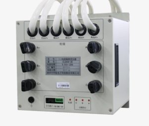
The ICT CL2030-D is used to provide a galvanic-free current to energy meters for testing and calibration purpose.
Each meter position on the rack has it's own ICT. Isolation Current Transformers are needed when the current-potential-links inside of the meter can't be opened.
More information here.
Our ICTs are also used with 3rd party meter test equipment. We have for the full information about this product a separate page.
Fill the form and get reply for this product to your email-inbox.
