
In the precise world of electrical energy measurement and distribution, a brief but potent phenomenon presents persistent challenges: inrush current. This initial surge of current, far exceeding normal operating levels, occurs when energizing inductive loads like transformers or motors. While momentary, its effects ripple through protection systems, metering accuracy, and equipment longevity. For professionals managing power networks, metering systems, and test laboratories, a clear grasp of inrush current remains essential.
The Physics Behind the Pulse
Inrush current arises from the fundamental behaviour of electromagnetic devices. When voltage is first applied to a transformer's primary winding, the magnetic core is initially unmagnetized. To establish the required magnetic flux (φ) opposing the sudden voltage change (governed by Faraday's Law: V = -N \frac{d\phi}{dt}), the system draws a large current. This current, limited primarily by the winding resistance and leakage inductance before the core saturates, can reach magnitudes 10 to 25 times the transformer's full-load rated current, or even higher for certain motor types (40x FLR not uncommon).
Several factors influence the magnitude and duration of inrush:
- Point-on-Wave Switching: The exact point in the AC voltage waveform when the circuit closes significantly affects the initial flux offset and thus the peak current. Closing near voltage zero maximizes inrush.
- Core Remanence: Residual magnetism left in the core from a previous shutdown can either mitigate or exacerbate the inrush depending on its polarity relative to the new energization.
- Core Saturation Characteristics: The design and material of the magnetic core dictate how easily it saturates, directly impacting peak current.
- System Impedance: The source impedance (including cabling and upstream transformers) limits the available fault current, which also caps the achievable inrush magnitude.
Consequences in the Field
This transient magnetization current, though typically lasting only a few cycles (milliseconds to tens of milliseconds), carries significant operational implications:
- Protective Device Nuisance Tripping: Circuit breakers, particularly thermal-magnetic types or sensitive electronic trip units, may interpret the high inrush as a fault current (e.g., short-circuit), causing unnecessary trips. This disrupts power supply and necessitates manual resetting.
- Voltage Sags & Flicker: The sudden high current draw causes a temporary voltage drop across the system impedance. This dip can affect sensitive equipment downstream and cause noticeable light flicker, potentially violating standards like IEC 61000-3-3.
- Mechanical Stress: The electromagnetic forces generated by high currents exert significant physical stress on transformer windings and busbars, contributing to long-term wear and potential failure.
- Metering Challenges: Traditional electromechanical meters and some electronic meters can over-register energy consumption during the inrush period. While the absolute energy error per event is small, frequent switching (e.g., in demand response or cyclic loads) can lead to cumulative billing inaccuracies over time. High-precision revenue metering demands immunity to these transients.
- Thermal Stress: Although brief, the high RMS current during inrush generates considerable I²R heating in windings and connections, adding to thermal cycling stress.
Mitigation Strategies
Managing inrush current requires tailored approaches:
- Sequential Energization: Staggering the start-up of large inductive loads prevents simultaneous inrush events overloading the source.
- Soft Starters & Variable Frequency Drives (VFDs): For motors, these devices ramp up the voltage and frequency gradually, dramatically reducing inrush.
- Pre-insertion Resistors or Reactors: Temporarily inserting impedance during the first few cycles of closing limits the current peak before being shorted out.
- Controlled Switching (Point-on-Wave Closing): Intelligent switchgear precisely controls the closing instant to minimize the initial flux offset, thereby reducing inrush magnitude. This is highly effective for transformers.
- Inrush Current Limiters (ICLs – NTC Thermistors): These devices offer high resistance when cold (limiting inrush) and low resistance when warm (normal operation), commonly used in smaller power supplies and electronics.
- Protective Relay Coordination: Setting relays with appropriate time delays or using relays with specific inrush restraint algorithms (harmonic blocking/restraint, waveform recognition) prevents nuisance tripping while maintaining fault protection. Relays detect the characteristic harmonic signature of inrush (high 2nd harmonic content) versus fault currents (fundamental dominant).
Testing and Metering Considerations
- Test Equipment Capability: Modern energy meter test systems must generate highly distorted transient waveforms, including inrush, to verify meter performance under realistic conditions. While specific immunity to inrush transients is often assessed under broader Electromagnetic Compatibility (EMC) standards (such as the IEC62052-11 series for voltage dips
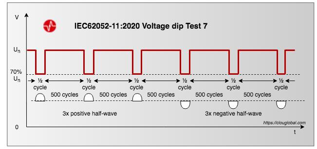 Short Interruption and Dip Tests IEC62052-11, short interruptions, and fast transients), the ability to simulate inrush current profiles allows for thorough functional testing. Portable test sets used in field verification require sufficient bandwidth and sampling rate to capture and analyse these brief, high-magnitude events accurately.
 - Meter Design: High-quality electronic energy meters employ sophisticated algorithms and high-speed sampling to differentiate between true energy consumption and the non-power-producing components of inrush current, ensuring billing accuracy. They must also maintain functionality and accuracy during the voltage sags that inrush events cause elsewhere on the network.
- Standards: Metering standards like IEC 62052-11 (general requirements) and IEC 62053-21 (active energy) define general testing conditions and accuracy classes. They reference EMC standards for immunity. Performance during transient disturbances like those caused by inrush is an implicit requirement for reliable revenue metering, driving the need for robust test methodologies.
For metering institutes and testing engineers, accurately characterizing and accounting for inrush is vital:
Takeaway
A clear understanding of inrush current is essential for anyone involved in power distribution and metering. At its core, inrush current results from the transient magnetization of inductive devices during energization, as described by Faraday's Law. These peaks can reach 10 to 40 times the nominal current and, although brief—lasting only milliseconds—can trigger a cascade of operational issues. Nuisance tripping of protective devices, voltage sags and flicker, mechanical and thermal stress on equipment, and even potential errors in metering are all common consequences. Effective mitigation relies on a combination of strategies, including sequential start-up, the use of soft starters or variable frequency drives, pre-insertion impedance, controlled switching, inrush current limiters, and well-coordinated protective relays. For those in the metering and testing field, it is crucial that modern meters are immune to these transients, that test equipment can accurately simulate inrush events, and that compliance with relevant standards is maintained. Ultimately, managing inrush current is not just a technical exercise—it is vital for maintaining the stability, accuracy, and longevity of power networks.
Join the Conversation
Have you encountered challenges with inrush current in your projects? What mitigation techniques or testing practices have worked best for you? Share your experiences or questions in the comments below—let's keep the discussion going and learn from each other's expertise.


All comments are moderated before being published. Inappropriate or off-topic comments may not be approved.