In the realm of electrical engineering, the effective conversion of mechanical energy into electrical energy is a crucial process. One method that accomplishes this feat is through the utilization of three-phase generators.
Michael Faraday discovered the electromagnetic induction. When you place a conductor in a varying magnetic field a voltage is induced by the EMF (electromagnetic force).
This principle is used in generators.
In our simplified example the generator consists of a rotating magnet (rotor) and of a stator with six conductor coils (A, A', B, B', C, C'). Between A, B and C is a shift of 120°. The conductors with an apostrophe are on the opposite side.
If the rotor N (north-pole) is matching with the stator A, we have maximum voltage amplitude in phase A (L1). When the rotor N reaches the A', we have the minimum amplitude.
This happens for all three phases. The sine waves are coming from the increase or decrease of the EMF on a single conductor. Monitor the wave generation in relation to the rotor position.
The rotating speed of the rotor gives us the frequency. When we want to have 50 Hz, the rotor has 50 revolutions per second.
In praxis it's not a static magnet. The electromagnetic force can be controlled much better when using an electromagnet.
Our portable test equipment 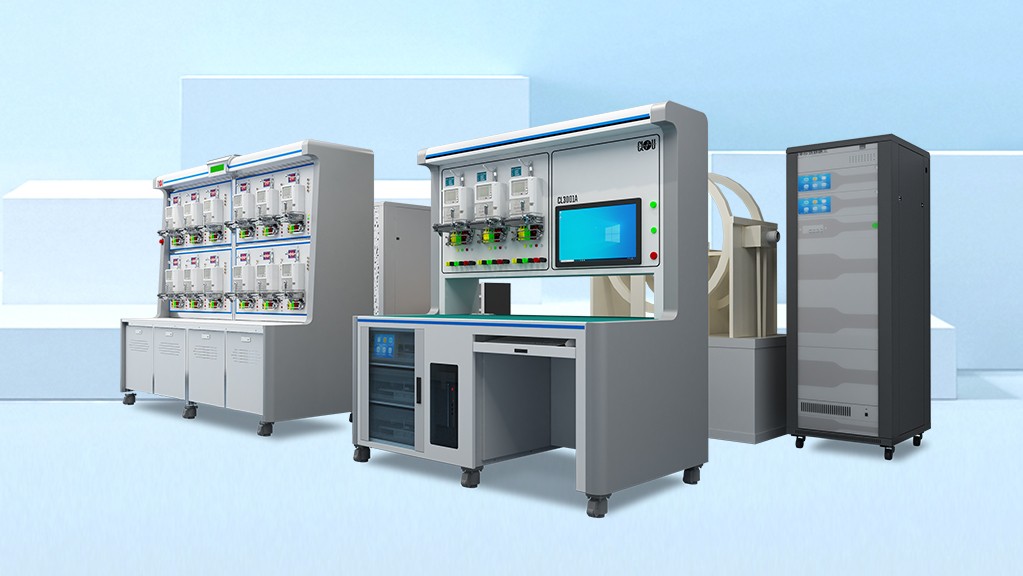 Introducing Our High-Quality Meter Test Equipment for Precise Measurements has many possibilities to check the power quality, e.g.total harmonic distortion
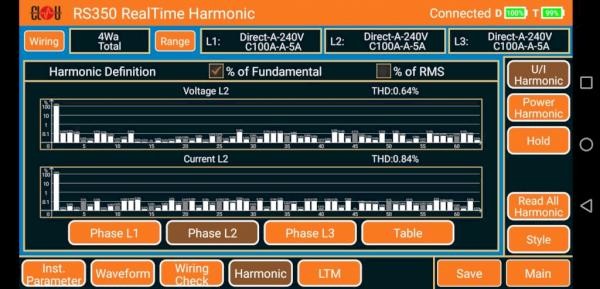 What are harmonics ?.
This post is to refresh the knowledge. We need this for the following articles.
Thank you for reading.
Editor's note: This article was originally published in November 2019 and has been updated for comprehensiveness.


All comments are moderated before being published. Inappropriate or off-topic comments may not be approved.