
When planning electrical power systems, the Crest Factor (CF) is an important element. Engineers may design more dependable and efficient power systems by understanding Crest Factor and how it impacts the grid.
What is a Crest Factor?
Crest Factor is the ratio of a waveform's peak amplitude to its RMS value. Under ideal sinusoidal conditions, it's √2 ≈ 1.414. The crest factor has no unit, it's only a numerical value.
The general calculation formula is
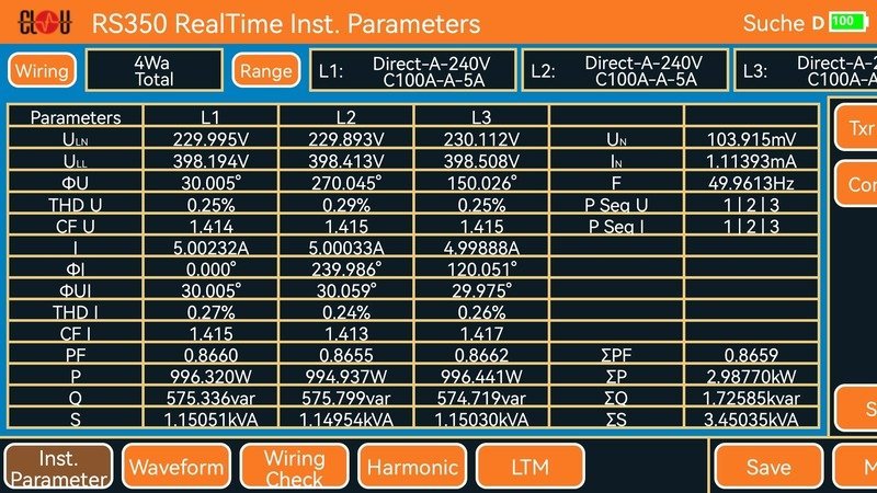
\text{Crest Factor CF} = \frac{|x_{\text{peak}}|}{x_{\text{rms}}}Advanced electrical measurement equipment, like our reference standards, are indicating the crest factors for all voltages and currents individually.
Crest Factor for Voltage (CF U)
Electrical power generators deliver sinusoidal voltage waveforms, but by the moment they reach the end user, they are typically not flawless.
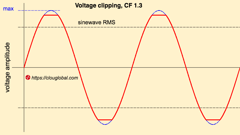
\text{Crest Factor} = \frac{|U_{\text{peak}}|}{U_{\text{rms}}}Clipping, sometimes termed as "Flat-Topping," is a persistent issue in electrical alternating current (AC) systems. It mostly happens at end-user installations behind the breaker switchboard, when the wire resistance is too high, coming from wire length and improper cross-section and using non-linear loads.
A typical example is a switch mode power supply without power factor compensation (PFC). Here, only the voltage peak is shaved or clipped, and we have a lower peak value. This leads to a crest factor lower than 1.414.
To monitor the voltage CF is an excellent approach to find potential electrical problems in a facility. For instance, if the voltage CF of an electrical circuit is close to 1.4 when the circuit is not loaded, but drops to less than 1.1 when an electronic load is connected, this could be a sign that the wiring of the circuit is either at or above its maximum power transfer capacity. Installing a new wire with a wider cross-section would be the appropriate solution in this situation.
Crest factor measurement can detect possible wiring and load issues, which a conventional voltage measurement can't. If you measure e.g. 227 V at a 230 V power line, it looks fine. If at the same time the voltage CF is below 1.4, you know that there is an underserved or overloaded circuit which can severely damage the connected equipment, because it doesn't get the maximum power.
Crest Factor for Current (CF I)
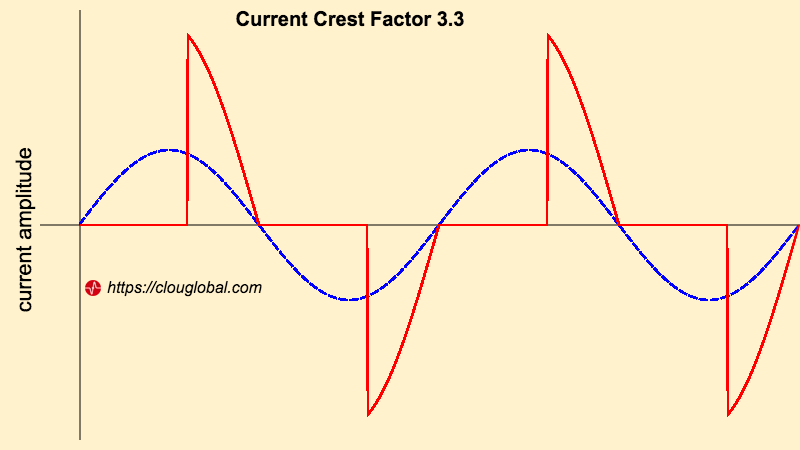
The voltage waveform is generated as a sine wave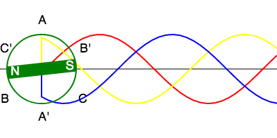 The Principle of Three-Phase Generators, while the current drawn by electronic loads may be sinusoidal. Pure resistive loads will pull a current in sine pattern (in blue, below, CF I = 1.414).
Especially, switch mode power supplies are pulling current in peaks (red line). Electronic loads without compensation can easily reach a CF larger than 3.
One problem of high current crest factors can be the moulded case circuit breaker (MCCB). These breakers have two trigger elements. The magnetic element protects against high overcurrents with durations of one cycle or more, while the thermal element triggers on heat. So, the short duration peaks will not lead to a magnetic tripping, but can cause a thermal disconnection due to the occurring heat in the peaks.
Takeaway
The crest factor can be used as additional indicator for the power quality in the grid. The impact on power transformers, circuit breakers and other elements like uninterrupted power supply (UPS) needs to be considered during the planning stage.
Editor's note: This article was originally published in October 2022 and has been updated for comprehensiveness.


All comments are moderated before being published. Inappropriate or off-topic comments may not be approved.