
![]()
 Safeguarding Yourself: A Guide to Personal Safety with Electrical Installations This article is for interested utility engineers. Don't make experiments at home. This will lead to tamper and can damage home appliances. Opening of the terminal cover is allowed by authorized utility staff only.
If you work with energy meters, always maintain the general safety rulesSafeguarding Yourself: A Guide to Personal Safety with Electrical Installations.
Since three-phase 3 wire meters don't need a neutral, the following applies for three-phase 4 wire meters only.
The Problem
The energy meter shows for a longer period (> 30 s) a reverse current, though there is no any power generation on load side.
A possible reason can be a high resistance or an interruption in the neutral wiring. This can come from:
- poor connection
- too small wire cross-section
- wrong or poor earthing
The Reason
Now it gets pretty much theoretical. We look at a wiring diagram first.
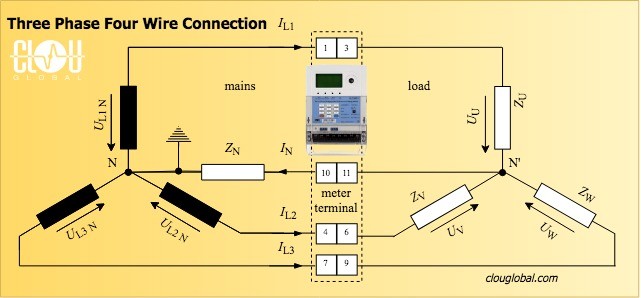
For sure, you remember the formula for the currents in three-phase meters with star connection.
This is simple Ohm's law.
Calculation for balanced load
Z = ZU = ZV = ZW (all resistances are the same)
Now we see, what we all have expected. If we have balanced or symmetric load, the sum current is zero.
Calculation for unbalanced Load
ZU ≠ ZV ≠ ZW (different resistances per phase)
If the impedance in Neutral (ZN) is zero, we can calculate the current in Neutral (IN) like this:
\displaystyle I_{\mathrm{N}} = I_{\mathrm{L1}} + I_{\mathrm{L2}} + I_{\mathrm{L3}} = \frac{U_{\mathrm{L1\,N}}}{Z_{\mathrm{u}}} + \frac{U_{\mathrm{L2\,N}}}{Z_{\mathrm{v}}} + \frac{U_{\mathrm{L3\,N}}}{Z_{\mathrm{w}}}If ZN ≠ 0, we have an impedance in Neutral. In this case the current in Neutral is:
\displaystyle I_{\mathrm{N}} = I_{\mathrm{L1}} + I_{\mathrm{L2}} + I_{\mathrm{L3}} = \frac{U_{\mathrm{N'\,N}}}{Z_{\mathrm{N}}}The current is particularly returned in the phases with lower load according to the Kirchhoff law. Now we have a reverse current. In case of missing neutral, the current will be distributed to the phases by 100%.
Neutral Point Shift
In addition, we have a Neutral point shift coming from the potential difference between the Neutral at transformer (N) and the Neutral at load (N').
We set up our known equitations first.
\displaystyle \frac{U_{\mathrm{N'\,N}}}{Z_{\mathrm{N}}} = \frac{(U_{\mathrm{L1\,N}} – U_{\mathrm{N'\,N}})}{Z_{\mathrm{u}}} + \frac{(U_{\mathrm{L2\,N}} – U_{\mathrm{N'\,N}})}{Z_{\mathrm{v}}} + \frac{(U_{\mathrm{L3\,N}} – U_{\mathrm{N'\,N}})}{Z_{\mathrm{w}}}Then we resolve the above equitation by UN'N.
\displaystyle U_{\mathrm{N'\,N}} = \frac{ \left( \frac{U_{\mathrm{L1\,N}}}{Z_{\mathrm{u}}} + \frac{U_{\mathrm{L2\,N}}}{Z_{\mathrm{v}}} + \frac{U_{\mathrm{L3\,N}}}{Z_{\mathrm{w}}} \right) }{ \left( \frac{1}{Z_{\mathrm{N}}} + \frac{1}{Z_{\mathrm{u}}} + \frac{1}{Z_{\mathrm{v}}} + \frac{1}{Z_{\mathrm{w}}} \right) }Now, that we have done the Math, we look at the effect.
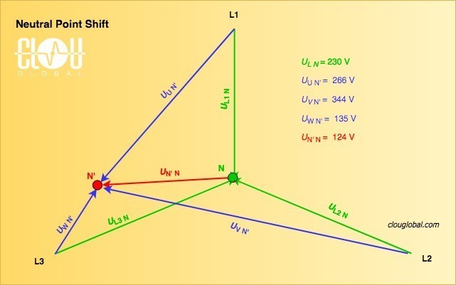
Green: mains side
Blue: load side
Red: shift
We see that the real problem of high resistance in Neutral is the shift of the Neutral point. This can lead to extreme phase-neutral voltage differences.
How to tackle the problem?
Check the wiring at the meter terminal. Be sure about your electrical power supply system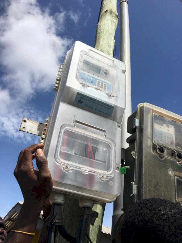 Electrical Power Supply Systems. Is the Neutral build from earthing only? In most cases, I saw temporary problems during a dry season when the Earth resistance is increasing.
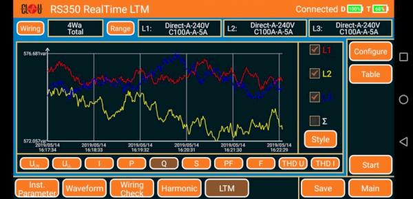
Use an on-site tester with advanced features like analysis of phase angles, monitor the vectorial diagram and run eventually a long time record to limit the causes of the fault.
What about the Energy Meter?
Our CLOU three-phase 4 wire energy meters have wide range power supply modules. They are powering up, even when the Neutral is missing.
Once the meter is powered up, it simply makes its job by sampling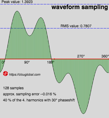 Waveform Sampling for Electrical Measurements the incoming values. The advanced meters have registers for bidirectional measurement.
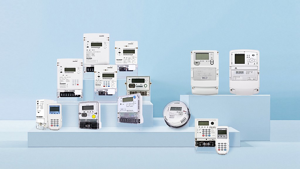 The four-quadrant diagram in electricity metering An arrow on the meter display shows flow in reverse direction
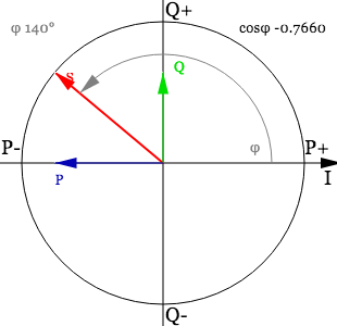 Negative Phase Current.
I saw in some tender specifications that the meter should operate normal under missing neutral conditions. So, we did extensive tests. The operation is normal, but with error variations.
There is no standard for error limits under these abnormal situations. The general findings are, that the error variations are below 1% for missing neutral, if all three phases are present. If in addition one phase is missing and the power factor is < 0.5, the error can vary up to 3.5% from the regular value in any direction depending on the load-point.
Still, I have to say that missing neutral is a safety risk due to high occurring voltages. It's also utility responsibility to make sure that the resistance in neutral is low. Each country has regulations, in Germany are 10 Ohm impedance allowed for Neutral earthing.
Thank you for reading and stay safe
Editor's note: This article was originally published in January 2022 and has been updated for comprehensiveness.


Dear REINHARD,
Thank you for your detailed response. After viewing your comments, I developed a Python script to simulate voltage behavior under varying impedance conditions.
I found that when the impedance is purely resistive, the shifted neutral point (N') remains within the triangle formed by phases L1, L2, and L3. However, when the impedance includes a reactive component, N' can shift outside this triangle.
TAM
Dear TAM,
Thank you for your follow-up and for rolling up your sleeves with a Python simulation—clearly, you don't just take diagrams at face value! That's the spirit I like to see.
Just a quick note: when I ran my own simulation (using trusty old JavaScript, because why not keep things lively?), I didn't bother with the "purely resistive" scenario. After all, in the real grid, finding a load that's 100% resistive is about as likely as spotting a unicorn at a substation. Most of what we see out there comes with a healthy dose of reactance, whether we like it or not.
So, your observation fits perfectly: if you keep things strictly resistive, the neutral point (N') behaves and stays inside the triangle. But throw in a bit of reactance, and suddenly N'is off on an adventure outside the triangle—just like in my JS simulation and in most real-world situations.
Thanks again for sharing your results and keeping the conversation both sharp and practical. It's always a pleasure to have a technical chat with someone who isn't afraid to get their hands dirty with code.
Dear Laoren,
Thank you for your explanation—it was very helpful.
I would like to ask a question regarding the diagram titled "Neutral Point Shift Example." In the graph, the shifted neutral point N′ appears to be located beyond the line connecting points L1 and L3.
Shouldn't N′ be positioned somewhere along or within the bounds of the line segment between L1 and L3, rather than beyond it?
Best regards,
TAM
Dear TAM,
Thank you for your kind words and for raising this question.
In the diagram, the shifted neutral point N′ does indeed appear beyond the line connecting L1 and L3. This placement is intentional and reflects the vector nature of the phase voltages in a three-phase system with an unbalanced load or a missing neutral.
The position of N′ is determined by the vector sum of the phase voltages and the load impedances. When there is a neutral shift, N′ can move outside the triangle formed by L1, L2, and L3, depending on the degree and direction of the unbalance. It is not restricted to the line segment between L1 and L3; rather, its position is defined by the resultant of the unbalanced phase voltages.
In practical terms, if one phase is more heavily loaded (or has a different impedance), the neutral point will shift towards the less loaded phases, and this can result in N′ being located outside the geometric bounds of the triangle formed by the phase points.
No coment
Thank you for saying that. I really appreciate the feedback!
THERE IS A THREE PHASE 4 WIRE SUPPLY SYSTEM TO A HOUSE HAVING UNBALANCE AS WELL AS ELECTRONIC LOAD. I NOTICED NEUTRAL CURRENT DUE TO UNBALANCE LOAD AND OVER AND ABOVE THERE IS THIRD HARMONIC CURRENT DUE TO LED LIGHT AND OTHER ELECTRONICALLY CONTROL LOAD. THIS RESULT IN NEUTRAL TO EARTH VOLTAGE NEAR TO 15 V.
CAN THIS AFFECT THE ENERGY RECORDING? AS WE ARE BILLED HIGHER EVERY MONTH.
Thank you for detailed description. Unbalanced load and harmonics are normal in the three-phase 4 wire system. Electronics energy meters are capturing the consumption including the occurring harmonics accurate. Means, your meter is in the allowed tolerance of +/- 1% (for a class 1 meter).
Your Neutral-Earth potential difference comes from poor earthing at your house or in your area and has no impact on billing.
My question was not fully answered – (Drawbacks = disadvantages not differences)
Comment if the expected life of meter will be reduced?
please review- you can email me alone
Thank you for additional comment. Since the accelerated life tests for three-phase meters are not based on single-phase connection, we don't have these data. IMHO the lifetime is the same, but without having the related tests we can't proof it.
Are there any other drawbacks of using a 3 phase meter (3P4W) to meter single phase load apart from high cost?
Can it reduce the expected life of the 3 phase meter?
There are no other differences to meter load via three-phase meters or single-phase meters. The three-phase meters support single-phase power supply. But while connecting the meter, you need to first check the meter relay status to avoid tamper, and check the working voltage range.