
Accurate current measurement is crucial in electrical engineering for various applications, ranging from power systems and industrial equipment to electronic energy meters. This article provides a comprehensive overview of the underlying mechanisms of different methods for current measurements in AC and DC circuits. We will discuss the pros and cons of each method to guide electrical metering engineers in selecting the most suitable current measurement technique for their specific needs.
Please be aware that the methods we discuss here are specifically relevant to our metering purposes, as we have received inquiries regarding this topic from our friends and users.
Shunt Resistors
Shunt resistors are commonly used in electrical AC and DC circuits to measure current. They provide a low-resistance path for the current flow, allowing a small voltage drop to be measured across the resistor, which is directly proportional to the current passing through it. The current is calculated using Ohm's Law (I = V/R).
The advantage of using shunt resistors for current measurement is their simplicity and cost-effectiveness compared to other methods. They can handle high current levels and offer a wide range of measurement options.
However, shunt resistors have a small voltage drop and can cause power losses in the circuit. Additionally, their accuracy can be affected by factors such as temperature variations and stray resistance, making careful adjustment The difference between adjustment and calibration, calibration and compensation necessary for precise measurements.
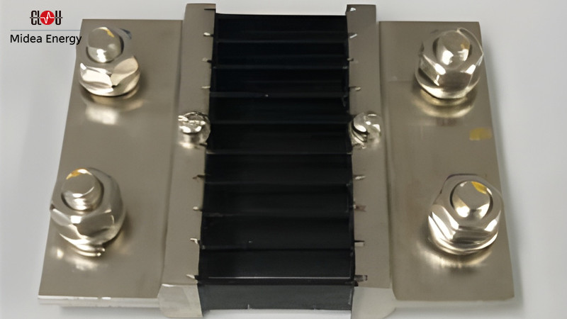
(image credit CLOU)
Current Transformers (CTs)
CTs offer several advantages in the field of current measurements. CTs provide accurate high-current measurements, allowing for precise monitoring and control of power systems. Their ability to transform high primary currents to lower, measurable secondary currents ensures reliable and accurate readings. Additionally, CTs provide electrical isolation between the primary and secondary circuits, enhancing safety by preventing direct contact with high-voltage currents. This isolation feature is particularly beneficial in ensuring operator and equipment protection during measurement operations.
Another advantage of CTs is their flexibility in current ratios. They are available in various ratios, enabling engineers to choose the appropriate CTs to match specific system requirements. This wide range of ratios allows CTs to accommodate diverse current magnitudes encountered in different applications, making them versatile and adaptable.
In terms of cost-effectiveness, CTs often present an economical solution for high-current measurements. Compared to alternative current measurement techniques, such as Hall effect sensors, CTs are generally more affordable without compromising on accuracy. This cost advantage makes CTs a preferred choice in many applications where accurate high-current measurements are essential but budget constraints exist.
A special solution are Clamp-on CTs. These devices use a current transformer-like mechanism, where the clamp-on unit is placed around the conductor. They provide non-intrusive measurements but are limited in accuracy and often suited for quick spot checks rather than precise measurements.
However, there are certain considerations and limitations associated with CTs. One such limitation is the frequency range for which CTs are designed. CTs operate optimally within specific frequency ranges, and their accuracy may deteriorate outside these ranges. It is crucial to select CTs that align with the operating frequency of the system to maintain accurate measurements across the entire frequency spectrum.
Saturation effects are another factor to consider. When the primary current exceeds a certain threshold, CTs can experience saturation. This saturation leads to distorted output currents and compromises measurement accuracy. Proper CT selection and design are necessary to ensure that CTs can handle the expected current levels without reaching saturation and causing measurement errors.
Also, the burden impedance connected to the secondary winding of CTs can influence their performance. Deviations from the specified burden impedance values may result in measurement errors and affect the overall accuracy of the CT. Therefore, it is crucial to carefully consider and adhere to the recommended burden impedance values to maintain precise measurements.
The physical size and weight of CTs should be taken into account too. Due to their construction and the need for robust insulation and magnetic cores, CTs can be bulky and heavy. This factor should be considered when planning for CT installations, ensuring adequate space and structural support are provided.
By considering these items, electrical engineers can make informed decisions when selecting and utilizing CTs for current measurements in power systems.
Rogowski Coils
The Rogowski coil is an important current measurement device widely used in electrical engineering for its unique function principle. It consists of a flexible coil with no solid magnetic core, which differentiates it from traditional current transformers (CTs).
The function principle of a Rogowski coil relies on Faraday's law of electromagnetic induction. When an alternating current flows through a conductor enclosed by the coil, a varying magnetic field is generated. This changing magnetic field induces an electromotive force (EMF) in the Rogowski coil, proportional to the rate of change of the current. This induced EMF is then integrated to obtain the actual current value.
The Rogowski coil offers several advantages, making it a popular choice for current measurements in various applications. Its flexible and open-loop design allows easy installation around conductors without the need to disconnect or break the circuit, making it suitable for retrofitting in existing systems. This feature also results in minimal impedance and no saturation issues, ensuring accurate measurements even at high current levels.
Rogowski coils also provide a wide bandwidth and excellent transient response, making them suitable for capturing fast-changing current signals and high-frequency components. Their fast response time is particularly advantageous for dynamic systems, power quality analysis, and fault detection in electrical networks.
Also, the absence of a solid magnetic core eliminates issues related to hysteresis and remanence that are common in traditional CTs. This advantage leads to improved linearity and a wider dynamic range for current measurements, enabling accurate readings across a broad spectrum of currents.
Nevertheless, Rogowski coils do have some limitations that should be considered in specific applications. Since they rely on the rate of change of the current, direct current (DC) measurements are not possible with Rogowski coils. External electronics are required to convert the output voltage to a meaningful current value, which adds complexity to the measurement setup.
In addition, Rogowski coils are more susceptible to external noise and electromagnetic interference compared to solid-core CTs. Proper shielding and signal conditioning are essential to mitigate these effects and ensure accurate measurements in noisy environments.
Temperature sensitivity is another notable consideration when using Rogowski coils for current measurements. Rogowski coils can be affected by changes in temperature, which may lead to variations in their output and impact measurement accuracy. The temperature sensitivity arises from the materials used in constructing the coil, such as the conductor and insulation. Variations in ambient temperature can cause changes in the coil's resistance and capacitance, affecting the coil's response to current signals.
Engineers must take these temperature effects into account during the design and calibration process to ensure accurate and reliable measurements. Some strategies to mitigate temperature-related issues include using temperature-compensated components, employing proper shielding and insulation techniques, and calibrating the Rogowski coil at the expected operating temperatures.
Hall Effect Sensors
Hall effect sensors are used to measure the strength of a magnetic field. When a magnetic field is applied perpendicular to a conductive material carrying a current, a voltage is generated across the material, which is perpendicular to both the direction of the current and the magnetic field. This is known as the Hall effect.
In a Hall effect sensor, a thin strip of conductive material is placed in a magnetic field. A current is passed through the strip, and the voltage across the strip is measured perpendicular to both the current direction and the magnetic field direction. The magnitude of the voltage is proportional to the strength of the magnetic field, which in turn is proportional to the current being measured.
The Hall effect sensor typically consists of a thin piece of semiconductor material, such as gallium arsenide, that is doped with impurities to create a conducting layer. The conducting layer is sandwiched between two layers of a material that does not conduct electricity, such as glass or plastic. The top and bottom of the sandwich are connected to electrical contacts.
When a magnetic field is applied perpendicular to the sensor, the electrons in the conducting layer experience a force that deflects their motion and creates a voltage difference between the two electrical contacts. This voltage is proportional to the strength of the magnetic field, which can be used to determine the current flowing through the sensor.
Hall effect sensors have several advantages that make them popular for a wide range of applications. One of the main advantages is their ability to provide accurate measurements of magnetic fields, even in harsh environments.
They are also highly sensitive to small changes in magnetic fields, making them ideal for detecting position, speed and direction in motors and other mechanical devices. Additionally, Hall effect sensors are non-contact, meaning that they do not require physical contact with the object being measured, reducing the risk of damage or wear over time.
Another advantage of Hall effect sensors is their low power consumption, which makes them ideal for use in battery-powered devices. They are also relatively small and lightweight, making them easy to integrate into a wide range of applications.
Hall effect sensors are versatile and can be used to measure a wide range of magnetic fields, including both DC and AC fields.
However, there are also some disadvantages to using Hall effect sensors. One of the main drawbacks is that they can be more expensive than other types of current measurement methods.
Hall effect sensors can be affected by external electromagnetic interference, which can lead to inaccurate readings. Also, they typically require a separate power supply and signal conditioning circuitry, which can add to the overall cost and complexity of the system.
Takeaway
Selecting an appropriate current measurement method is fundamental in electrical engineering applications. Shunt resistors, CTs, Rogowski coils and Hall effect sensors offer various advantages and disadvantages. Each technique should be carefully evaluated based on factors such as measurement range, accuracy, bandwidth, environment, safety considerations, and cost. By understanding the underlying principles and weighing the pros and cons, electrical engineers can make informed decisions and ensure accurate current measurements for their specific applications.
Thank you for taking the time to read. We welcome and encourage you to share your thoughts and feedback in the comments section below.
Editor's note: This article was originally published in July 2023 and has been updated for comprehensiveness.


All comments are moderated before being published. Inappropriate or off-topic comments may not be approved.