
The load current can vary frequently with high amplitude. The test conditions in the older versions of the IEC62052-11 have all be static e.g. related to In or Imax. The edition 2 of the standard has now introduced a new test to cover the meter accuracy behaviour under fast load current variations.
These variations can happen by using air conditioners, regulated heaters, arc welding systems and other devices pulling a high current.
By the Committee findings some meter designs have significant accuracy errors under such conditions, mainly coming from the current range switching.
The Fast Current Load Variation Test is intended to verify the meter accuracy by using different duty cycles.
The Test in Detail
The voltage circuits are energized with their highest specified nominal voltages.
- a) the test current shall be repeatedly switched between on and off states
- b) during the ton period, the value of the test current shall be as given in the relevant particular requirements (accuracy class) standards
- c) during the toff period, the value of the test current shall be equal to zero
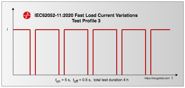
- d) the duration of the ton and toff periods shall be according to the following test profiles:
1) ton = 10 s, toff = 10 s, total test duration 4 h
2) ton = 5 s, toff = 5 s, total test duration 4 h
3) ton = 5 s, toff = 0,5 s, total test duration4 h - e) the turn-off times and the turn-on times do not need to be synchronized with the zero crossings of the mains frequency. The switching between on and off states shall occur within one cycle at nominal mains frequency. The tolerance for ton and toff shall be +/- one cycle at nominal mains frequency;
You need to take care of the item e):
The idea is to switch on and of within one cycle at any state of the sine-wave. This switching needs to be randomized over one cycle while we need to monitor the voltage cycles as reference and for cycle counting.
The recommended method for accuracy verification is the meter energy comparison with a reference standard. It's the same procedure as a register test with the accuracy limits given in the particular requirements of the meter under test.
The test set-up
We suggest you use a voltage/current source for test value generation. Then you need to make a relay-box with two three-phase load switches What is a Load-Switch?, same as used in energy meters.
The meter under test (UUT) is looped through the reference standard while you are using a second meter of the same type for returning the current during the OFF periods.
The switching timings are controlled by a small programmable micro-controller (e.g. Arduino). With the microcontroller, you can easily randomize the switching within +/-20 ms.
It's also no bad idea to count the total number of relay switching for a relay reliability test.
Be creative :)
What?
Yes, we are also meter test equipment manufacturer. But this relay-box is too simple and the paper-work for doing the certification process and documentation stands in no relationship with the expected sales figures.
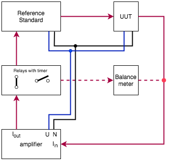
suggested principle solution
Other solutions are possible.
The diagram shows the principle based on a single phase set-up.
The reference standard is set to do a register test. You switch on the voltage, read the UUT register, switch the current on and start the relay box controller.
After 4 hours you switch the current off, make a second reading of the UUT and evaluate the error.
You have to do this for each test profile individually.
The test profiles


The Error evaluation
\displaystyle error = \frac{(meter\ reading – reference\ reading)}{reference\ reading} \cdot 100%The IEC62052-11 acceptance criteria A apply.
The meter is PASS when your calculated error is within the accuracy class limits and the meter internal load switch (relay) hasn't operated unexpected.
Of course you will not sit there and monitor 12 hours fast load current variations. So, after the test you check the meter event log for eventually operations during your test period.
Hint: Set the reference standard to the required current range to avoid eventual energy incrementation loss due to range switching.
Thank you for reading. Do you have another approach for this test? Maybe you like to share your experience.
Editor's note: This article was originally published in July 2020 and has been updated for comprehensiveness.


All comments are moderated before being published. Inappropriate or off-topic comments may not be approved.