
![]()
 Safeguarding Yourself: A Guide to Personal Safety with Electrical Installations The audience for this post are technical engineers and meter installers from power companies and utilities. Meter users are not allowed to open the terminal cover for legal- and for safety reasons!
I've got recently a nice photo with a good example, how to connect an energy meter wrong. Each utility has its own installation procedures, and all of them have in common:
- Choose the right wiring cross-section
- Fasten the screws tight
Wiring Cross-section
| Energy Meter | Cross Section | Breaker or Fuse |
|---|---|---|
| Imax = 40 A | 6 mm2 | 40 A |
| Imax = 60 A | 16 mm2 | 63 A |
| Imax = 80 A | 25 mm2 | 80 A |
| Imax = 100 A | 35 mm2 | 100 A |
Source: VDE 0100 Part 430
The given values are the best praxis for single copper wires in a cable tray or tube with an ambient temperature of 30°C.
Maintaining the right cross-section avoids overheating and is also reducing the internal resistance. Higher cross-section will reduce the technical loss Technical vs Non-Technical Losses: What You Need to Know, but this is a more commercial question.
The calculator below can give you a rough indication for reducing the loss. For the calculations we are using the double wiring length (to the consumer and return).
| Power Loss Calculator | |
|---|---|
| Distance to consumer | |
| Cross-section | |
| Nominal Voltage Un | |
| Current | |
| Cable resistance (Cu) | Ω |
| Load resistance | Ω |
| Total resistance | Ω |
| Voltage-drop | V |
| Loss | VA |
Fastening of the terminal screws
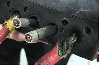
On the photo we can see that the terminal 4 is particular melted.
The other three terminals are looking fine and since the current in the system was the same, the melting wasn't coming from choosing a wrong cross-section.
Either the terminal screws have particularly clamped the wire insulation or the screws haven't been tightened fixed. When I look at terminal one, I assume that the cables coming from the mains (utility) haven't been proper uninsulated.
For the standard nerds: The big terminal screws (M5) need a torque of 2.5 Nm while the small screws (M3) should be fastened with a torque of 0.5 Nm.
For the signal terminals (M2.5) a torque of 0.4 Nm is recommended.
You remember that copper tends to shrink over the time. When you are on site for meter calibration, just check also that the terminal screws are fastened tight. You will reduce your utilities technical loss.
Thank you for reading.
Editor's note: This article was originally published in June 2021 and has been updated for comprehensiveness.


All comments are moderated before being published. Inappropriate or off-topic comments may not be approved.