
The IEC 62052-11 Ed.2 comes with a lot of changes for meter type testing. Another new introduced test for electromagnetic compatibility (EMC) is the ring wave immunity test.
The test method is described in IEC 61000-4-12. Here is only a brief overview for the required meter tests.
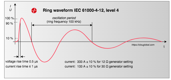
These tests verify the energy meter performance under the influence of power surges, coming from lightning or load switching at substations.
The waveform
Test procedure
Firstly, you energize the voltage circuits with their highest specified nominal voltages. The connection cable length is defined with 1 m.
Then you read the active- and reactive SUM registers with high resolution The Energy Meter Register Resolution. We need the readings later for the Pass/Fail evaluation.
All following tests have to be done with transients (our ring wave) at phase angles of 0°, 90°, 180° and 270°of the fundamental AC voltage waveform.
Five positive and five negative transients shall be applied at a rate of one transient per minute, at each specified phase angle.
So, the testing time for each of the following tests is 40 minutes. The tests are described for a direct connected three-phase four wire meter.
Test of the main meter terminals
a) You set the generator impedance to 12 Ω. Then you test between each line, including neutral, and ground with 4 kV. We take the mains-in terminals and have the disconnection relay closed. Total duration excluding wiring change is 160 minutes.
b) Now we are testing in differential mode each line to line and each line to neutral with 12 Ω and 2 kV. Means:
– L1 vs. L2
– L1 vs. L3
– L1 vs. N
– L2 vs. L3
– L2 vs. N
– L3 vs. N
As we are testing with both polarities, this set will cover all possibilities for our three-phase four wire meter. Total duration excluding wiring change is 240 minutes.
HLV signal ports
HLV means Hazardous Live Voltage. By IEC 62052- 31 these are voltages > 33 V RMS.
Auxiliary input- or output circuits are e.g. terminals for external relay control. Before doing the tests you need to be clear about the voltage terminal ratings.
The tests need to be done
a) between each line and ground with 12 Ω and 2 kV
b) in differential mode, line between line with 12 Ω and 1 kV
Potential-free contacts are tested in differential mode only.
ELV signal ports
ELV stands for Extra Low Voltage. These are terminals of auxiliary input or output circuits, data communication circuits and other auxiliary circuits rated for voltages < 33 V RMS.
The tests are done in common mode with 30 Ω and 0.5 kV. Common mode means, simultaneous coupling to all lines versus the ground.
We are building two signal groups:
a) all communication terminals are connected simultaneously
b) all signal ports are connected simultaneously
Total duration excluding wiring change is 80 minutes.
Pass/Fail Evaluation
Acceptance criteria: B, the IEC wordings are in Italic
During the test, a temporary degradation or loss of primary functions is acceptable:
a) energy registration: at any time during the test, and immediately after, the value of energy registers shall not change by more than the critical change value;
At any time during the test is from my point of view not practicable. It's sufficient to check the registers after all test are finished.
The Committee has also realized this and put a foot-note:
NOTE For tests of effects of external influence quantities or disturbances (9.3 and 9.4), constant monitoring of the indicating display during the whole duration of a test is not always feasible. In such cases it is sufficient to monitor the indicating display only when there is a reasonable doubt that the indicating display of the EUT may be susceptible to a particular influence quantity. The determination of such conditions is left to the expertise of the testing laboratory.
For evaluation, you read the SUM registers and compare the change versus the critical change value. The Critical Change Value
b) indicating display: degradation of display quality (colour, brightness, contrast, sharpness, geometry, etc.) during the test is acceptable; the indication of the content of energy registers may become unreadable during the test;
Nothing to do for evaluation.
c) supply and load control switches: unexpected operation of the switch during the test shall not occur.
You can either listen for several hours whether the relay makes the typical switching sound or your check the log-file for relay operation during your testing period.
During the test, a temporary degradation or loss of other meter functions within the scope of this document is acceptable, including a self-recovering reset of embedded software (firmware).
After the test when the disturbance is removed, and the reference test conditions are restored, the meter shall show no damage and shall operate with additional percentage error not exceeding the limits specified in the relevant particular requirements (accuracy class) standards.
That's clear, I suggest doing the test with all items mentioned in the IEC 62058-31 Acceptance tests for energy meters for inspection.
All meter functions within the scope of this document shall be restored without any intervention of the operator, and without removal of the mains supply or the auxiliary power supply.
This means, you need to do the function tests at the ring wave generator station before you power down. Good that the IEC is stating this at the very end.
All meter functions within the scope of the IEC62052-11 Ed2. will take some time. I wonder what you are going to test?
Thank you for reading. As this test is newly introduced for energy meters, maybe we can have some mind exchange.
Editor's note: This article was originally published in August 2020 and has been updated for comprehensiveness.


Dear Laoren,
If you are applying all the ELV signal lines against the GRP, it looks to me like an isolation test which is not the main goal of this EMC test. In my opinion, there are many possible interpretations:
1) The meter is consider as a doble-isolated product, so the Ring Wave test shouldn't be done on ELV signal lines (except if the meter has a PE terminal).
2) Otherwise, the Ring Wave test for ELV SIGNAL lines applies having as a common reference any of the following: (i) PE terminal; (ii) Neutral for instruments installed with TN-S Grounding systems;
3) There is a 3rd reference point that can be used as a common reference to apply Ring Waves in ELV signal lines: the GND!! Although in my personal opinion, the GND terminal is just a digital reference for communication purposes, some colleagues arguing that Ring Wave overvoltages can be induced in ELV signal lines by indirect coupling paths, therefore, the right way to simulate such cases is applying Ring waves between TX, RX to GND terminal (0,5 kV) and TX to RX (0,25 kV).
Dear Laoren, please let me know your opinion on those 3 possible interpretations.
Best regards,
Juan Carlos
Dear Juan Carlos,
I appreciate your input regarding the testing considerations. Based on the guidelines outlined in IEC62052-11:2020 #9.3.10, there are no exceptions mentioned. Consequently, I propose disregarding your first and second points. However, I agree with your argumentation concerning the third point.
The objective of the test is to ensure proper functionality, particularly in terms of energy registration and display (as specified in acceptance criteria B). We are simulating an induction from the mains, so the option of TX and RX versus GND can be considered, potentially serving as an isolation test as well. As for RX versus TX, we can exclude it based on the wording of the IEC, which refers to the signal group.
Upon further consideration, it occurred to me that we do not have an ELV auxiliary power supply port in your case, while the test is described as auxiliary power versus signal ports. Perhaps we are overcomplicating matters.
For personal interest, I intend to investigate this case further with some type-test laboratories. I will keep you updated on any findings.
Once again, I appreciate your highlighting of this.
Best regards,
Laoren
Hello
I would like to know how this test is performed on the communication/signal ports of an energy meter.
According to the text you presented, on ELV signal ports, the disturbance is simultaneously coupled to all lines versus the ground. Consider an energy meter which has a reference ground on its communication/signal port and this terminal is isolated from the meter's neutral terminal. My question is: where is the disturbance generator ground connected? Is It connected to the communication port reference ground or to the energy meter neutral?
In other words, will the reference ground for the communication port be subjected to the disturbance in the same way the other communication terminal are (like TX, RX, RTS, etc)? Or it works as the reference of the disturbance generator?
Thank you for your question, Paulo. The IEC isn't very clear for this case. We are testing all communication ports, including the communication GND, versus the ground reference plane (GRP).
Dear all, con you provide for information and analysis, a calibration report of this device?
We would like to check how is calibrated to evaluate conformity with the standard
Thank you for your comment, Dario. The article describes, how to conduct a ring wave immunity test for energy meters according to IEC 62052-11 Ed.2. We are not the manufacturer, we are users. Our actual equipment is an EM Test OCS 500N6-series. This equipment was initially calibrated by the manufacturer and annually calibrated by our local metrological institute. I'm sure that either your metrological institute or the manufacturer can give you insights for conformity.