
When it comes to transformer-operated energy meters, instrument transformers play a crucial role in reducing high voltage and current values to lower quantities for accurate measurement purposes. In the context of power distribution, we encounter different voltage levels as defined by IEC 60038:
- Low voltage (LV): voltages up to 1 kV
- Medium voltage (MV): voltages between 1 kV and 35 kV
- High voltage (HV): voltages between 35 kV and 230 kV
In this article, we'll focus on the selection of low voltage current transformers (CTs).
A current transformer works by producing a secondary current that is proportional to the primary current. It consists of a single primary winding window through which an external bus-bar or cable runs. CTs are commonly used for metering and protection purposes.
When selecting a CT, there are several key considerations to keep in mind:
a) The primary current rating
The primary current rating of a CT should be larger than the expected maximum operating current. For metering CTs, the primary current rating should not exceed 1.5 times the maximum operating current. Standard values for the primary current (Ipr) include 10, 12.5, 15, 20, 25, 30, 40, 50, 60, 75 A, and decimal multiples of these values (as per IEC 60044-1).
b) The secondary current rating
CTs typically have a secondary current rating of either 1 A or 5 A. While CTs with a 5 A secondary rating are becoming less common due to the rise of digital CT driven equipment, CTs with a 1 A secondary rating are often preferred for minimizing transformer and secondary cable size, especially for long secondary cables. In some countries, instrument transformers with a rated secondary current (Isr) of 10 A or 20 A can still be found.
c) The voltage level
Transformer-operated CT/VT meters measure on the primary side of distribution transformers and require isolation from medium voltage on the primary side. CT-operated meters, on the other hand, are connected to the secondary side of the distribution transformer and receive the secondary voltage (e.g., 230 V) and the transformed current (e.g., 5 A).
d) Indoor/outdoor use and connection
Outdoor CTs should have the same ingress protection (IP) rating as the distribution transformer. Additionally, the CT window must match the cable diameters or bus-bar size for proper connection.
e) Rated real output power (burden)
The output power, also known as burden, needs to be calculated for each measurement setup. If the CT's output power is too low, the meter may either display no value or provide a lower reading than necessary for accurate measurement. Utilities typically have standard installation plans to determine the appropriate burden.
Calculation
wire-resistance-calculation:
\displaystyle R = \frac{l}{\kappa \cdot A}power-calculation:
\displaystyle P = I^2 \cdot Rcurrent-transformer-burden-calcualtion:
\displaystyle P = I^2 \cdot \frac{l}{\kappa \cdot A}
R: resistance in Ω
l: total length in m
(to the meter plus return to the CT)
κ : conductivity in m/( Ω*mm2)
copper has a conductivity of 57 m/(Ω*mm2)
A: cross-section of the conductor in mm2
I: secondary current or the CT in A
P: output power in VA
Once we have the burden, we need to add 1 VA for the consumption of electronic energy meters. For electromechanical meters we need to add 3 VA.
You can use the calculator below to see the impact of the different parameters on the CT burden. The calculation is based on copper wires and reference temperature 20°C.
| CT burden calculator | |
|---|---|
| Secondary current Isec | |
| Wire cross-section | |
| Total length of the cables | |
| Wire burden | |
| Meter Burden | 1 VA |
| Total |
Standard values for CTs are: 1, 2.5, 5, 10, 15 VA. You will choose the next higher burden rating after your calculation
f) Accuracy class
The accuracy class indicates the accuracy of the CT's secondary current within a range from 5% to 125% of the rated primary current. Beyond this range, the CT may start to saturate, resulting in the secondary current being clipped to protect the inputs of the connected metering instrument. Accuracy classes such as Cl. 1.0, Cl. 0.5, and Cl. 0.2 are commonly used for metering and billing purposes. It's important to note that the CT is part of the measurement circuit, so if you have a CT meter with a class 0.5 S and a CT with a class 1.0, the maximum error at that measurement location will be ± 1.5%. Choosing CTs with a better accuracy class can help minimize potential losses, but the decision ultimately depends on the utility's budget and objectives.
g) Frequency
The CT's frequency rating must match the system's operating frequency. Standard frequencies are 50 Hz and 60 Hz. While a 50 Hz CT can be used in a 60 Hz system, a 60 Hz CT cannot be used on a 50 Hz system.
By considering these key criteria, you can make an informed selection of low voltage current transformers that meet your specific requirements for accurate and reliable measurement.
Installation hints
![]() Never leave the secondary side of a current transformer open. It can cause a high voltage of several kV. You can find a good description for the reason here.
Never leave the secondary side of a current transformer open. It can cause a high voltage of several kV. You can find a good description for the reason here.
We recommend the use of "test disconnect terminals".
Always maintain the general safety rules Safeguarding Yourself: A Guide to Personal Safety with Electrical Installations.
Once the installation is complete, it is crucial to ensure the proper functioning of the entire system by conducting a meter error measurement using primary current. If anything seems suspicious during this process, it is important to investigate the transformer ratio, burden, and meter error individually.
There are some common mistakes that can occur, such as using the wrong energy meter ratio, incorrectly wiring the current transformers (CT) in an inverted manner, or overloading the CT with excessive burden.
One classic mistake that often arises after installation is increasing the burden. This occurs when a backup meter is added later or when someone wants to compare consumption with an electromechanical meter. While the comparison may appear to be faultless, the total power of the current transformers may not be sufficient to support the operation of two or more energy meters in series.
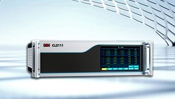
To verify the accuracy of installations with current transformers, we highly recommend using portable meter test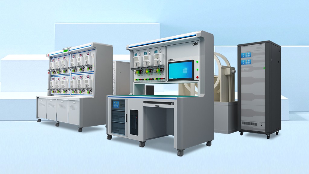 Introducing Our High-Quality Meter Test Equipment for Precise Measurements equipment. Regular verification of these installations is essential.
Thank you for taking the time to read this. If you have any inquiries or need further information about meter installations and verification, please do not hesitate to reach out to us Contact Us. We are here to assist you and welcome your valuable thoughts and comments.
Editor's note: This article was originally published in September 2020 and has been updated for comprehensiveness.


Happy to read your good article about metering in Medium and High Voltage. In fact, our factory started around 1905 in Chile to manufacture this called "Meter Out Fit" I started around 1977, and was send to study to UK, London 1966 to the Morgan Group.I left CARR Company and started PROGOS. I make this comment cause from2 years ago we make this Meter Out Fit in China, oil and dry type within our own name.
Today, are using REv Meters from Schneider, very very expensive, is the reason we want to replace by yours with data for revenue plus Power Quality.
I have one question for you, why some big markets do not use this CT&PT Combined and sell directly in Low Voltage, having a lot of Tech losses?Tariffs on low voltage ( 4% higher than to buy in Medium voltage and KW ON and OOF PEAK is 2 times more expensive.
Thanks again and congratulations, hope this help another partners from abroad.
Thanks for comment, Mariano.
The power companies have different strategies. Especially in deregulated markets with different companies for power generation, transmission and distribution a combined solution is difficult to implement. You can also find a certain lag of knowledge or interest in innovations inside those companies.