
Energy metering has never been done for fun. There is money involved, so the meter accuracy has to be verified.
In the past without any electronics it was really challenging. You needed a voltage/current source with a high stability, calibrated wattmeters and a calibrated stop-watch.
The source was transformer operated with regulators for current, voltage and phase shift.
First you adjust voltage and current. Then you read the power from the wattmeters.
The meters connected to the test bench had to be tested one by one.
Each meter has a meter constant, indicating the no. of revolutions per kWh.
Imagine a single-phase meter with a constant of 75 r/kWh. We have adjusted the voltage to 230 V and the current to 10 A. Power factor is 1.
We see on the wattmeter a power of 2300 W.
Now we can calculate the theoretical time for one rotation based on the meter constant.
\displaystyle theoretical\ time = \frac{1000 \cdot 3600}{P \cdot c}P = power
c = meter constant
The theoretical time for one rotation under a power of 2300 W is 20,87 s. (Note that we had no calculator, in best case we calculated with a slide rule.)
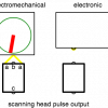
Next step: We stop the time for one rotation. The rotating disk of the electromechanical meter has a coloured mark. Once the mark is in front of the meter you start the watch and you stop it once the mark reaches the same position after one revolution.
Let's say, you stop a time of 21.1 seconds.
Now we use the common formula for percentage error:
\displaystyle percentage\ error = \frac{experimental\ value – theoretical\ value}{theoretical\ value} \cdot 100%So we come to an error of +1.1% . The meter is faster than it should be. At that time the meters had typically an accuracy class 2, so it's PASS.
As you can see there are a lot of influence factors which can spoil the measurement result like
- inaccurate reading from the wattmeter
- source instability (wattmeter needle is moving during the test)
- inaccurate reading from the stop-watch
- too late or too early stopping of the time
- rounding errors in the calculations
Especially the stopping time made the life for the meter testers very hard. So the trick was to stop the time for several revolutions to minimise the human error for start/stop.
If you have portable equipment with a start/stop switch you can compare the error results vs. using a scanning head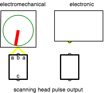 How does a scanning head work?.
Small exercise
In the animation below we see the rotating disk of a single-phase meter (top view without meter case ). This meter has a constant of 100 r/kWh. It's running with a load of 3,450 W.
You have already calculated the theoretical run time per revolution (10.43 s).
Use your satellite synchronised smart phone stop watch to check the meter error.
Leave me a comment with your result :)
In one of the next blogs Principle for Accuracy Testing of Energy Meters we'll see how much easier and faster a meter test is with modern meter test equipment
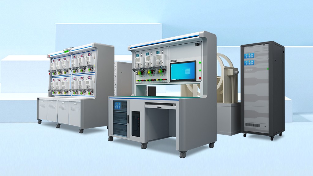 Introducing Our High-Quality Meter Test Equipment for Precise Measurements and testing software
 Electrical Measurement Studio EMS5. The basics still remain the same.
Thank you for reading.
Editor's note: This article was originally published in December 2019 and has been updated for comprehensiveness.


After performing the accuracy test the results were negative power factor meaning voltage ⚡️ was leading so how do one fix this
I suppose you are still referring to the CT meter installation we discussed earlier. When you have import, your power factor will always be positive, regardless of whether the voltage is leading (inductive) or lagging (capacitive). Given that you have a negative power factor, I'm quite certain that one or more CTs are connected in reverse. Please have a look at our four-quadrant measurement simulation to better understand the situation. Additionally, examining the phasor or vector diagram within the audit tool will help point you in the right direction.
Hello again REINHARD–
Somehow I think maybe I'm not explaining my concern very well. I will try again.
In your example above, the test case you present tells us nothing about the maximum current the meter is capable of measuring. All the accuracy test looks at is how closely the experimental value matches the theoretical value, (which is assumed to be exactly correct). The problem I am needing to get clarity about is that, from a practical perspective, it is not going to be possible to get the same accuracy, when measured in this way, from a meter that is capable of measuring 5000A as it is from a meter that is only capable of measuring 200A. If you run 10A through each of those meters, the 200A meter is going to give a more accurate reading than the 5000A meter. This is true whether we're talking about CT connected meters or directly connected meters. Somewhere the maximum current measuring capacity of the meter needs to be taken into account.
The analogy would be with weight scales. We cannot expect a truck scale to give us as accurate a weight for a chicken we're purchasing, as the scale at the meat market. If our only criteria for testing was what percentage difference there was between the known reference standard weight and the weight as measured by the scale, for say, a 20 lb weight on a truck scale, the scale would not be able to be certified as accurate. Somewhere the maximum weight measuring capacity of the scale needs to be taken into account.
Hello Doug,
Thank you for your patience and for giving me the opportunity to clarify this further. Let's look into the specifics of CT (Current Transformer) meters and their accuracy:
CT meters measure current on the secondary side of the instrument transformers, typically receiving standardized secondary currents like 10A, 5A, or 1A. For example, if the primary current is 200A or 5000A, the CT scales this down to a standard secondary current (think of it like converting a large weight on a primary scale to a manageable weight on a secondary scale).
How It Works:
– Transformer Ratio: The CT meter receives a secondary current (e.g., 10A), representing a primary current based on the CT ratio. If the CT ratio is 20:1, 10A secondary equates to 200A primary. If the ratio is 500:1, the same 10A secondary equates to 5000A primary. The ratio is programmed into the meter for accurate computation (similar to how a weight converter would work: 10 kg on a secondary scale represents 200 kg on a primary scale with a 20:1 ratio).
– Secondary Measurement: The meter measures the secondary current (10A) with high accuracy, typically within 0.2% or 0.5%, ensuring accurate primary current readings within the CT's specified range.
Now, let's address the errors introduced by CTs and the importance of the entire measurement setup.
– Nominal Accuracy: CTs have a specified accuracy class (e.g., 0.3% error at maximum load), which can be higher at low load (like a weight scale's precision).
– Burden: The load (burden) on the CT affects its accuracy. Long wiring or low cross-section wiring can cause the CT to not deliver the full 10A to the meter, leading to unpredictable errors (similar to placing a weight scale on an uneven surface).
– Phase Displacement and Temperature: These factors, like external influences on a weight scale, impact CT performance.
In summary, the accuracy of a measurement with CT meters is influenced not just by the meter itself, but also by the CTs and the entire measurement setup. It's essential to ensure both the CT and the conditions of the setup are optimal for precise measurement.
3 phase meter ct meter reading after audit was -97.55% both on 0.06 wh/I and 0.06 varh/I
Ct 200/5A
What conclusions can one say under this ?
A reading of -97.55% for both 0.06 Wh/I and 0.06 varh/I on a 3-phase CT meter with a CT ratio of 200/5 A indicates a significant discrepancy. Here are a few potential conclusions and areas to investigate:
– Test Equipment Connection: Make sure that the test equipment is properly connected. Before conducting error measurements, observe the vectorial diagram to ensure the correct phase relationship and connection integrity.
– CT Polarity: Ensure that the CTs are connected with the correct polarity. A reversed CT connection can cause substantial errors in the meter readings.
– Meter Configuration: Verify that the meter is correctly configured for the CT ratio of 200/5 A. An incorrect setting can result in erroneous readings.
– Connections and Wiring: Inspect all connections and wiring for any loose or faulty connections. Poor connections can introduce errors in the measurements.
Given the substantial error, it's advisable to perform a thorough on-site inspection to identify and rectify the issue. These checks should help pinpoint the cause of the discrepancy and ensure accurate meter readings.
Thanks REINHARD,
Yes, we're talking about external CT meters, but the meters are evaluated as a meter/CT unit. What I don't understand is how a meter with a range of 5000A can be held to the same accuracy, if calculated acording to your explanation, as a 200A meter. If you run both at 10A at 230V, how is it reasonable to expect that a meter that is capable of measuring 500x the current it's tested at, will be as accurate as a meter that is only capable of measuring 20x the test current? With everyday multimeters (VOMs) there are ranges, and to expect a multimeter to give as good results, measuring something around say 10V, if you use the 600V range as if you use the 20V range, would be unreasonable.
Thank you for your follow-up!
To break it down simply, let's consider a meter with an accuracy class of 0.5S and a nominal current In of 10 A. This means the meter is calibrated to maintain its accuracy up to 12 A (120% In). To achieve this, our test benches use internal reference standards with multiple current ranges. Specifically, we utilize 13 current ranges to ensure a reference standard accuracy of 0.05% over the entire current range (up to 120 A).
When using CTs (Current Transformers) in an installation, it's essential to recognize that the overall system accuracy will differ from the meter's accuracy alone. While the meter itself has a maximum error of ±0.5% (in our example), the CT introduces additional error. Therefore, to determine the total error of a specific installation, an on-site measurement is required.
During on-site testing, you'll measure the total current on the primary side. Your testing device will then provide the total error, factoring in the CT's contribution. It's also important to note that when measuring high currents with clamp-on CTs, these clamps have various ranges as well.
For more detailed information, I recommend reviewing our article on selecting Current Transformers.