
DLMS stands for Device Language Message Specification,
a generalised concept for abstract modelling of communication entities
Official website
The COmpanion Specification for Energy Metering
sets the rules, based on existing standards, for data exchange with energy meters, used together with DLMS
The idea of DLMS is to have a object oriented data structure. This allows a certain degree of interoperability between the head end system and meters from different manufacturers. DLMS has also specified the methods of data encryption and security. Only DLMS compliant meters are allowed to have the DLMS logo on the name plate.  DLMS compliant
Some examples for DLMS OBIS codes
Instantaneous Voltage
Phase voltage is measured and presented in corresponded DLMS/COSEM objects for each phase separately. Internally voltages are always measured in mV.
Instantaneous voltage is measured in the meter every second.
| OBIS codes | L1 | L2 | L3 |
|---|---|---|---|
| Instantaneous voltage | 32.7.0 | 52.7.0 | 72.7.0 |
Instantaneous Current
Phase current is measured and presented in corresponded DLMS/COSEM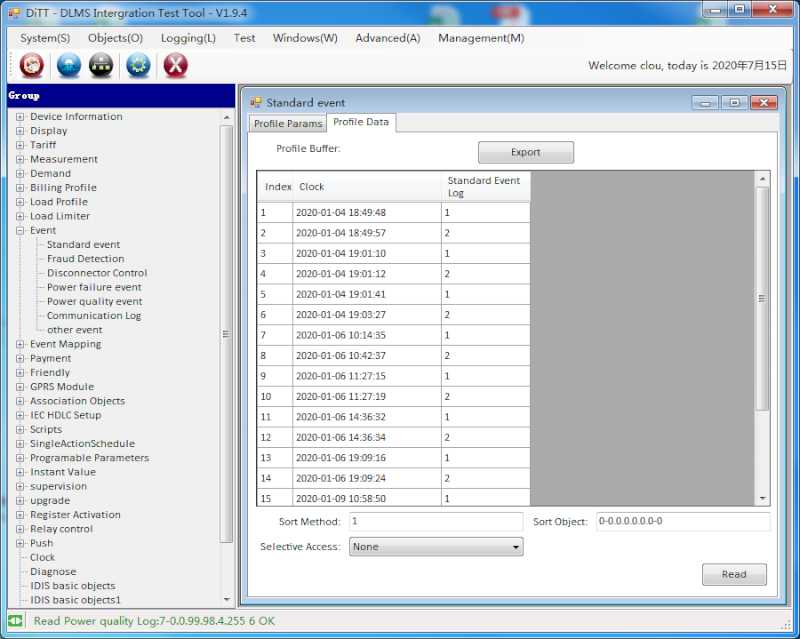 What is DLMS/COSEM ? objects for each phase separately. Internally currents are always measured in mA.
Instantaneous current is measured in the meter every second.
| OBIS codes | L1 | L2 | L3 | Sum |
|---|---|---|---|---|
| Instantaneous current | 31.7.0 | 51.7.0 | 71.7.0 | 90.7.0 |
Instantaneous Power
The measurement micro-controller sends the measured values approximately every 100 ms. Each instantaneous power value is available per phase and sum over all phases. All phase instantaneous power values can be calculated by vector or arithmetic method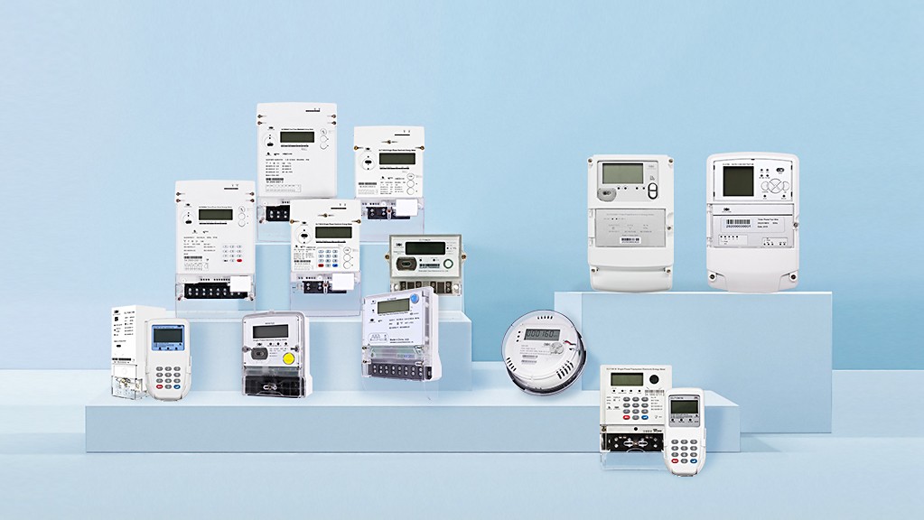 Calculation methods for energy. Not all CLOU meters have this functionality.
| OBIS codes | L1 | L2 | L3 | Sum |
|---|---|---|---|---|
| A+ | 21.7.0 | 41.7.0 | 61.7.0 | 1.7.0 |
| A- | 22.7.0 | 42.7.0 | 62.7.0 | 2.7.0 |
| Q+ | 23.7.0 | 43.7.0 | 63.7.0 | 3.7.0 |
| Q- | 24.7.0 | 44.7.0 | 64.7.0 | 4.7.0 |
| Q1 | 25.7.0 | 45.7.0 | 65.7.0 | 5.7.0 |
| Q2 | 26.7.0 | 46.7.0 | 66.7.0 | 6.7.0 |
| Q3 | 27.7.0 | 47.7.0 | 67.7.0 | 7.7.0 |
| Q4 | 28.7.0 | 48.7.0 | 68.7.0 | 8.7.0 |
| S+ | 29.7.0 | 49.7.0 | 69.7.0 | 9.7.0 |
| S- | 30.7.0 | 50.7.0 | 70.7.0 | 10.7.0 |
| ABS = |A+|+ |A-| | 35.7.0 | 55.7.0 | 75.7.0 | 15.7.0 |
| NET = |A+|- |A-| | 36.7.0 | 56.7.0 | 76.7.0 | 16.7.0 |
Average Voltage
Values of average phase voltages in settable aggregation period for voltage peak and minimum calculation are available as COSEM objects. Values in those objects are refreshed at the end of the measurement period and the same values are kept until the next period ends.
| OBIS codes | L1 | L2 | L3 |
|---|---|---|---|
| Average voltage | 32.24.0 | 52.24.0 | 72.24.0 |
Voltage Levels
Recorded when the duration for the voltage is more than 1 minute.
| OBIS codes | L1 | L2 | L3 | any |
|---|---|---|---|---|
| Level 1: > +10% | 128.7.11 | 128.7.21 | 128.7.31 | 128.7.41 |
| Level 2: between +10% and +5% | 128.7.12 | 128.7.22 | 128.7.32 | 128.7.42 |
| Level 3: between +5% and 0% | 128.7.13 | 128.7.23 | 128.7.33 | 128.7.43 |
| Level 4: between 0% and -5% | 128.7.14 | 128.7.24 | 128.7.34 | 128.7.44 |
| Level 5: between -5% and -10% | 128.7.15 | 128.7.25 | 128.7.35 | 128.7.45 |
| Level 6: between -10% and -15% | 128.7.16 | 128.7.26 | 128.7.36 | 128.7.46 |
| Level 7: < -15% | 128.7.17 | 128.7.27 | 128.7.37 | 128.7.47 |
Voltage Sag
When the rms voltage is below the nominal voltage by 10% to 90% for 0.5 cycles to 1 minute this event is called a sag.
Voltage sag 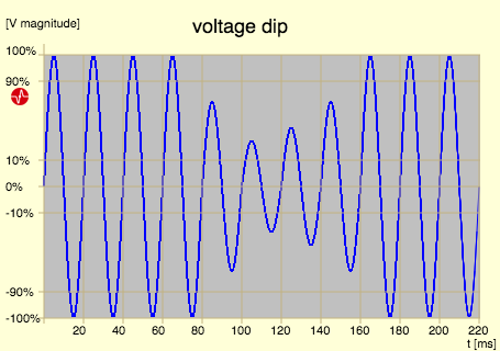 What is a Voltage Dip Event?starts when instantaneous voltage of specific phase drops below the threshold for Voltage Sag for longer than the time set. Voltage sag ends when the same instantaneous voltage rises above threshold for Voltage Sag.
Voltage sag detection involves 2% hysteresis, which means that once voltage drops below threshold , it must rise 2% above threshold in order to come out of voltage sag condition. The following information is recorded when voltage sag is detected:
- voltage sag counter is incremented by 1
- magnitude of voltage sag is stored
- duration of voltage sag is stored
- event is recorded in Power Quality Log
The threshold is defined as percentage of nominal voltage.
Time threshold for voltage sag specifies the required duration in seconds for which specific voltage must drop below voltage sag threshold until voltage sag condition is triggered.
| OBIS codes | Any |
|---|---|
| Magnitude for voltage sag | 12.34.0 |
| Under-limit duration | 12.33.0 |
| Counter for voltage sag | 12.32.0 |
Magnitude of last voltage sag
In this objects are the magnitudes of the last sags recorded.
Each detected voltage sag on specific phase voltage results in increment of corresponding phase voltage sag counter. The counter for any phase voltage sag is only incremented when all phase voltages come out of voltage sag condition.
Information on voltage magnitude for last occurred voltage sag on specific phase is stored in corresponding register object. For each phase meter records the minimum value of instantaneous phase voltages during voltage sag condition on that specific phase. The any phase voltage sag magnitude is registered when all phase voltages come out of voltage sag condition. The registered magnitude is the minimum measured instantaneous voltage in any phase during any phase voltage sag condition. With each new occurrence of specific voltage sag, previous voltage sag information is rewritten with new information.
In parallel with voltage sag magnitude, also voltage sag duration is recorded (per specific phase and for any phase). Duration records the time from the point that voltage level drops below voltage sag threshold to the point when it rises above voltage sag threshold including 2% hysteresis.
| OBIS codes | L1 | L2 | L3 |
|---|---|---|---|
| Magnitude of last voltage sag | 32.34.0 | 52.34.0 | 72.34.0 |
Voltage Swells
When the RMS voltage exceeds the nominal voltage by 10% to 80% for 0.5 cycles to 1 minute, the event is called a "swell".
Voltage swell 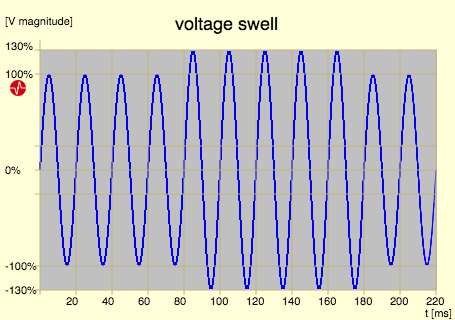 What is a Voltage Swell Event?starts when instantaneous voltage of specific phase rises above the threshold for longer than the time set in time threshold.
Voltage swell ends when the same instantaneous voltage drops below threshold. Voltage swell detection involves 2% hysteresis, which means that once voltage rises above threshold, it must drop 2% below in order to come out of voltage swell condition. The following information is recorded when voltage swell is detected:
- voltage swell counter is incremented by 1
- magnitude of voltage swell is stored
- duration of voltage swell is stored
- event is recorded in Power Quality Event Log
The threshold is defined as percentage of nominal voltage.
Time threshold for voltage swell specifies the required duration in seconds for which specific voltage must rise above until voltage swell condition is triggered.
| OBIS codes | Any |
|---|---|
| Magnitude for voltage swell | 12.38.0 |
| Over limit duration | 12.37.0 |
| Counter for voltage swell | 12.36.0 |
Magnitude of last voltage swell
Each detected voltage swell on specific phase voltage results in increment of corresponding phase voltage swell counter. The counter for any phase voltage swell is only incremented when all phase voltages come out of voltage swell condition.
Information on voltage magnitude for last occurred voltage swell on specific phase is stored in corresponding register object. For each phase the meter records the maximum value of instantaneous phase voltages during voltage swell condition on that specific phase. The any phase voltage swell magnitude is registered when all phase voltages come out of voltage swell condition. The registered magnitude is the maximum measured instantaneous voltage in any phase during any phase voltage swell condition.
With each new occurrence of specific voltage swell, previous voltage swell information is rewritten with new information.
In parallel with voltage swell magnitude, also voltage swell duration is recorded (per specific phase and for any phase). Duration records the time from the point that voltage level rises above Vv_swell to the point when it drops below Vv_swell including 2% hysteresis.
| OBIS codes | L1 | L2 | L3 |
|---|---|---|---|
| Magnitude of last voltage swell | 32.38.0 | 52.38.0 | 72.38.0 |
Magnitude of last voltage swell
Maximum demand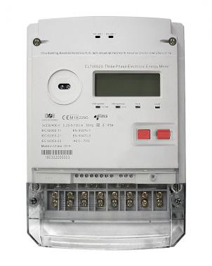 What is Maximum Demand Measurement? registers are storing the highest actual average value measured in each period. At the end of each period the actual average value from 1.0.x.4.0 registers are compared with the maximum demand value. If the actual average demand value is higher than the maximum demand value, it replaces the value stored in the maximum demand register.
Maximum demand values are set to zero value at the end of each billing period.
Maximum demand can be calculated for:
- active energy in both directions
- reactive energy per quadrant and as sum of two quadrantsThe four-quadrant diagram in electricity metering
- apparent energy in both flow directions
The tariff 1…8 is indicated by i.
| OBIS Codes | Sum | Tariff |
|---|---|---|
| A+ | 1.6.0 | 1.6.i |
| A- | 2.6.0 | 2.6.i |
| Q+ | 3.6.0 | 3.6.i |
| Q- | 4.6.0 | 4.6.i |
| S+ | 9.6.0 | 9.6.i |
| S- | 10.6.0 | 10.6.i |
Under-voltage/over-voltage
The meter detects condition when phase voltage rises above or drops below certain threshold levels. Such conditions are categorized as over-voltage or under-voltage. From samples of phase voltages the meter calculates the average values over a time period. This time period is synchronized with the meter clock. At the end of time period, each value of average phase voltage is compared to the over-limit and under-limit threshold parameters. When specific phase voltage value rises above over-limit threshold, an event for voltage over-limit is generated. Also when certain phase voltage drops below under-limit threshold, an event for voltage under-limit is recorded.
The meter also records end of voltage under/over limit condition (voltage normal event) when phase voltage returns between the two threshold levels. In order to prevent several events when phase voltage is exactly on the level of thresholds, a 2% hysteresis is implemented. This means that in order to detect normal voltage, phase voltage must rise an additional 2% above the under-limit threshold, or drop 2% below the over-limit threshold.
| OBIS codes | Any phase |
|---|---|
| Threshold for voltage over-limit | 12.35.0.1 |
| Time threshold for voltage over-limit | 12.44.0.1 |
| Threshold for voltage under-limit | 12.31.0.1 |
| Time threshold for voltage under-limit | 12.43.0.1 |
Maximum Demand Register
Maximum demand registers are storing the highest actual average value measured in each period. At the end of each period the actual average value from 1.0.x.4.0 registers are compared with the maximum demand value. If the actual average demand value is higher than the maximum demand value, it replaces the value stored in the maximum demand register.
Maximum demand values are set to zero value at the end of each billing period.
Maximum demand can be calculated for:
– active energy in both directions
-reactive energy per quadrantThe four-quadrant diagram in electricity metering and as sum of two quadrants
– apparent energy in both flow directions
The tariff 1…8 is indicated by i.
| OBIS identifiers | Sum | Tariff |
|---|---|---|
| A+ | 1.6.0 | 1.6.i |
| A- | 2.6.0 | 2.6.i |
| Q+ | 3.6.0 | 3.6.i |
| Q- | 4.6.0 | 4.6.i |
| S+ | 9.6.0 | 9.6.i |
| S- | 10.6.0 | 10.6.i |
Editor's note: This article was originally published in July 2019 and has been updated for comprehensiveness.


GRACIAS SIGO SUS INTERENSANTES Y UTILES ENSEÑANZAS
Gracias
Me puede ayudar a disponer de una hoja de cálculo.xlsx con todas las variables. Gracias
Puede obtener esta tabla desde la organización DLMS.