
The IEC 62052-11 Edition 2 has introduced some changes for the meter marking and documentation. Today we cover the mandatory content of the nameplate for IEC meters. If the meter has an MID approval, the content is slightly different and not covered by this post.
This text is in conjunction with section 6 of the IEC.
Usually there is no nameplate any more, markings are lasered on the front side of the meter case.
Symbols shall be at least 2.75 mm high. Text shall be at least 1.5 mm high and contrast in colour with the background.
A meter shall bear all the markings required by local regulations. In addition, and if not already required by the local regulations, the meter shall also bear the following information as applicable:
Mandatory Items on the name plate or case
1. Manufacturer's name or trademark
e.g. CLOU Electronics
2. Designation of Type
Given IEC examples are: "kWh meter", "kvarh meter", "energy meter", "smart meter"
Typically, we are using the CLOU type identifier and the designation:
e.g. CL730S23 Three Phase Electronic Energy Meter
The designation of type shall be preferable in local language.
3. Space for approval mark
Mostly an approval mark is already part of the nameplate during manufacturing process. In case the utility wants to attach their calibration/approval mark later, the name plate or case must have sufficient space.
4. Meter serial no. and year of manufacture
The serial number can be additionally shown as bar-code.
The year of manufacturing is sufficient. We usually add also the country.
E.g. Made in China 2020
5. Protective Class
The protective class is shown as symbol. Our meters have protective class 2.
The symbol looks like this 
6. Rated impulse voltage Uimp
e.g. Uimp = 6 kV
(You know that dimensions are written in Italic acc. to ISO 80000-1.)
7. Utilization category (UC)
If the meter has a load switch What is a Load-Switch?, the utilization category must be indicated.
e.g. UC3
8. Reference to Standards
Indicated are only the standards for the particular requirements.
e.g.
IEC 62053-21 Ed.2.
IEC 62053-23 Ed2.
We add the edition of the standards to make clear that we are fulfilling the latest requirements if the type test report is issued based on Ed.2.
9. Auxiliary power supply
If the meter has auxiliary voltage supply the value and frequency must be stated.
10. Connection and wiring diagrams
The connection diagram shall show where the supply control and load control switches and the internal power supply are connected. If there is no sufficient space, the symbol ISO7000-1641 may be used.
The connection diagram can also be placed on the inside of the terminal cover.
11. Mains terminals
As long as the mains terminals are designed to carry the maximum current, they don't need to be marked with a current rating. Nevertheless, each terminal must have a unique identification number. For meters with DIN terminals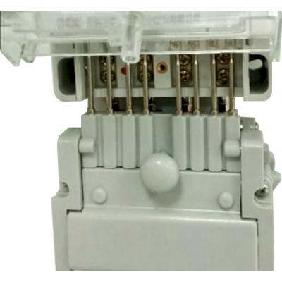 Terminal wiring for electrical energy meters the numbering is given in the DIN 43857 series. BS terminal are usually numbered incrementing from left to the right.
12. Auxiliary terminals
All auxiliary terminals must be easy identifiable, usually by number or inscription. The documentation must provide the additional required information.
13. Protective class and earthing (grounding)
If the meter doesn't have an earthing terminal, this item is already covered by #5 of this list.
14. Switches
The position of any switch must be clearly indicated. For the load switch we are doing this in the display (connected, disconnected, ready for connection if applicable). The Caution symbol ISO 7000-0434B marks that additional safety information is described in the manual. 
15. Batteries
Close to the slot for the exchangeable battery the same symbol as #14 of this list indicates that more safety relevant information can be found in the documentation.
16. Nominal voltage(s) or voltage range
e.g. 3 x 230/400 V
17. Service type
This is the symbol for the measuring elements. Three-phase four wire meter
18. Nominal current and current range
For a direct connected meter the minimum current, nominal current and the maximum current is indicated like this: Imin – In (Imax)
E.g. 0.5 – 10(40) A, for a meter having a minimum current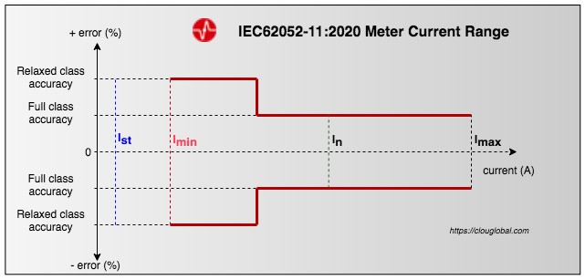 Where is the Basic Current? of 0.5 A, nominal current of 10 A and a maximum current of 40 A. The current indication is now the same as for MID meters.
19. Nominal frequency
e.g. 50 Hz
20. Meter constant
The meter constants are indicated close to the pulse output The Optical Test Output and Pulses LEDs. The expression is e.g. 500 imp/kWh for active and 500 imp/kvarh for reactive.
21. Accuracy class index
E.g. Cl. 1
If the meter has an active and a reactive test output it's recommended to write the accuracy class close to the diode and the meter constant.
22. Specified operating temperature range
E.g. -25°C to 55°C
23. Instrument transformer ratio
If the ratio is programmable, it must be shown in the display. If it's fixed, it will be indicated on the nameplate. The symbol for instrument transformer is shown on the case.
24. Special type information
If the voltage of the tariff control device differs from the nominal voltage, this shall be marked on the meter or on a separate plate.
Additional symbols
The IEC wording:
The applicable symbols specified in this subclause shall be marked on the meter case, an external nameplate, dial plate, external labels or accessories, or shown on the indicating display as appropriate.
We have e.g. Bidirectional
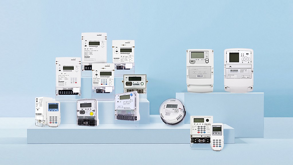 The four-quadrant diagram in electricity metering energy meter
 Bidirectional energy meter, always counting import
 Port in accordance with a specific standard like
IEC 62056-21, Mode C, IEC 62056 DLMS/COSEM What is DLMS/COSEM ?This symbol should be close to the optical port
Summary
Electronic energy meters are nowadays too complex to mark everything on the case. To give additional information the IEC requires
– information on the packing
– an instruction manual
– a user manual
– a maintenance manual
For referring to the manuals the case must show:The Caution symbol in the nameplate area.The Caution symbol close to the battery slot.The Caution symbol on the terminal cover
A "Read the Manual" symbol.
Final thoughts
Take care of the markings. Utilities are buying meters from various vendors. If the markings are not IEC compliant it can cause confusion.
I personally do not like when the markings are too small. The meter installers will be thankful to have clear information when working in dark basements.
Thank you for reading.
Editor's note: This article was originally published in August 2020 and has been updated for comprehensiveness.


All comments are moderated before being published. Inappropriate or off-topic comments may not be approved.